Aviation Connector Housing, Pins and Plating: Material Selection
What aviation connector housings, pins and platings are made of, how gold silver and tin plating change contact life, and what to specify for OEM orders.
Read More
A 10 pin aviation connector is the workhorse size when a machine needs several signals and a bit of power in one round cable — lighting control, machine sensors, small hoists, audio-visual rigs and automation panels all land on the 10-pin point. This guide covers how the 10 contacts are numbered, a practical pin allocation example, what current each pin realistically carries, and the assembly steps that keep a 10-circuit cable reliable for years instead of months.
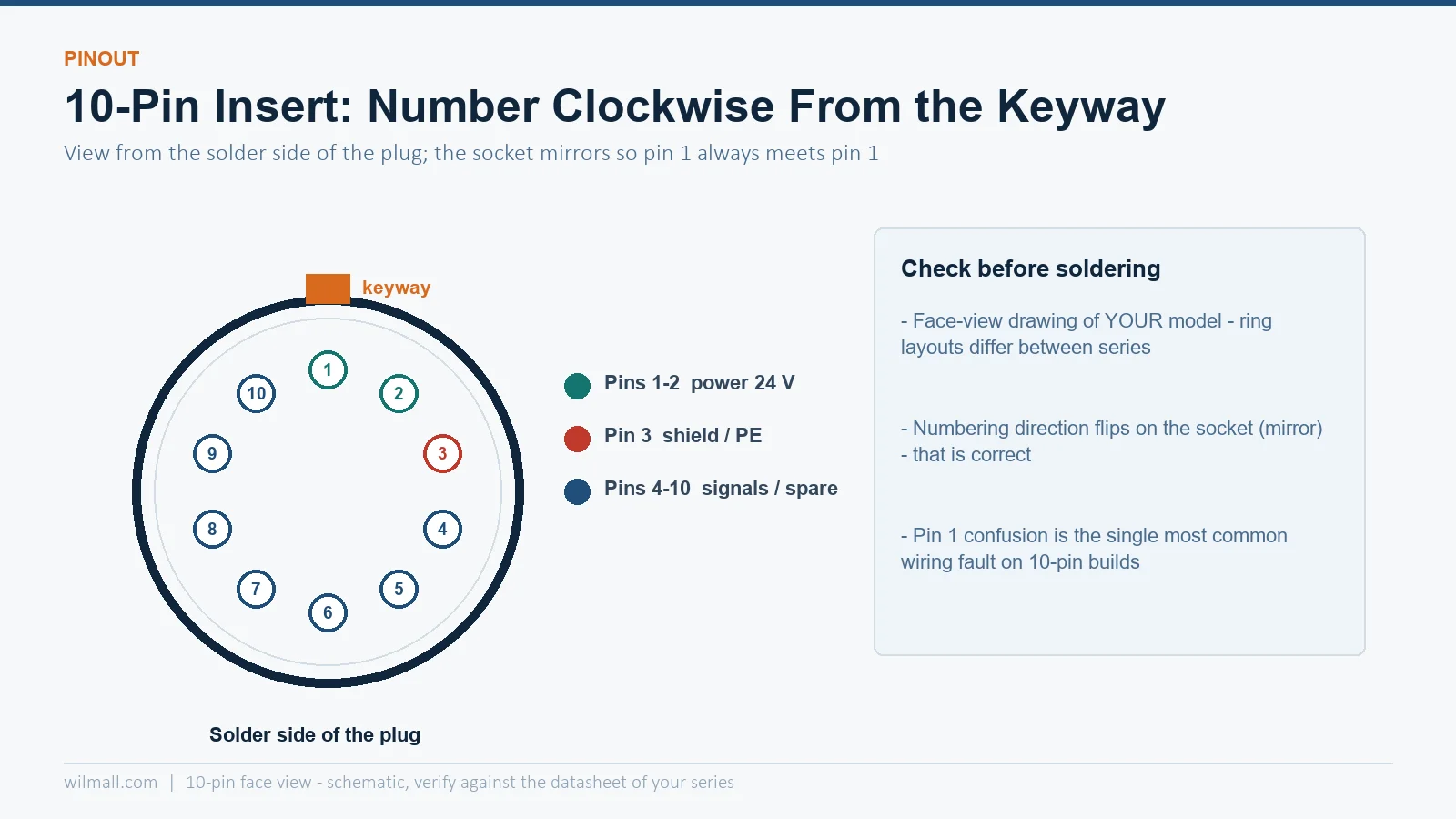
Round aviation connectors (GX/LD/SD series and their international equivalents) number contacts by convention, not by random layout:
Before soldering anything, look at the manufacturer’s face diagram for your exact model — the numbering rule above holds across most Chinese GX/LD series, but the physical ring layout differs between 2-ring and 3-ring inserts.
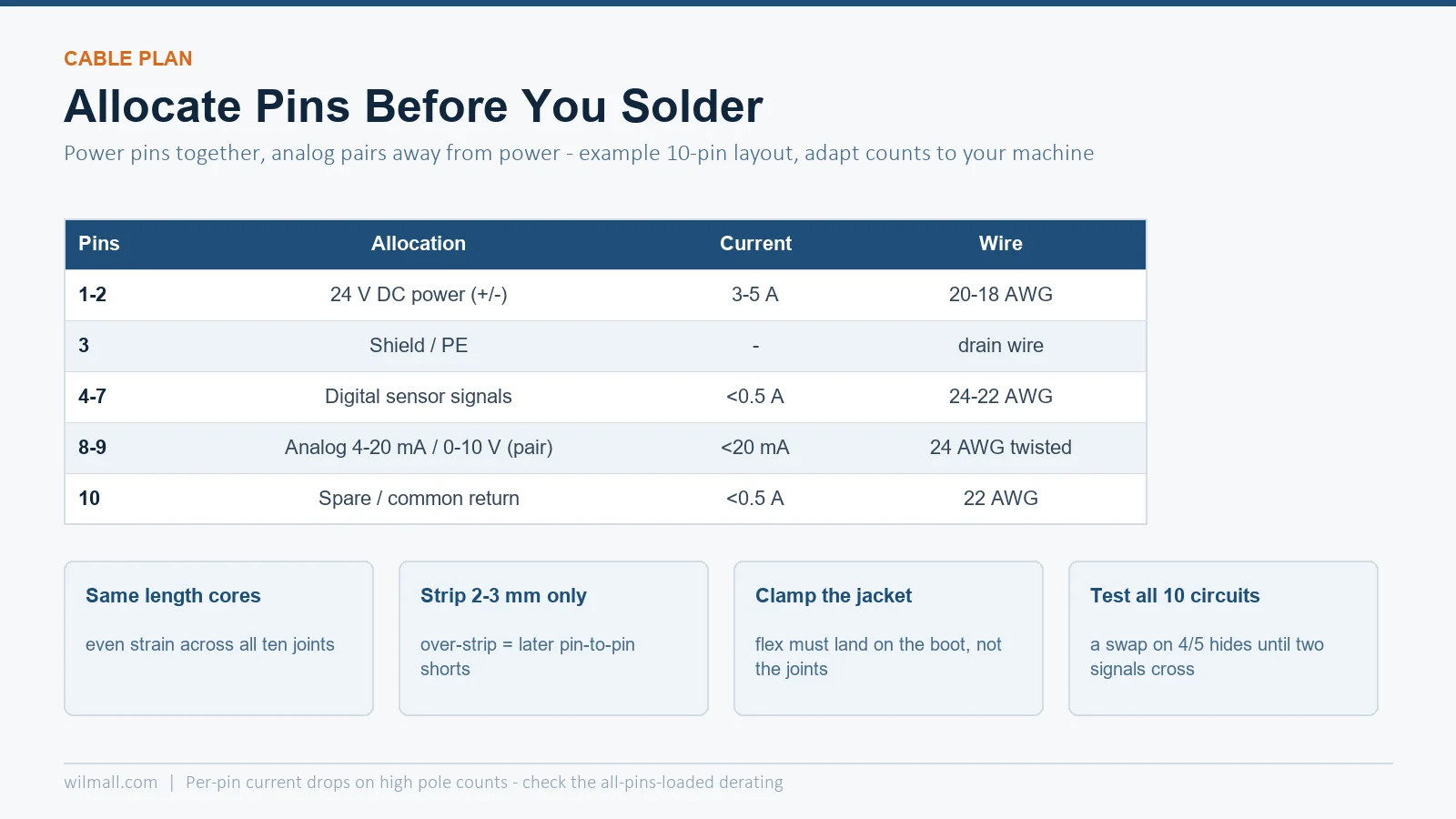
The biggest reliability gain in multi-pin cables comes from planning the allocation instead of filling pins in order. A proven pattern for a 10-pin cable that carries both power and signals:
| Pin | Allocation | Expected current | Wire gauge |
|---|---|---|---|
| 1–2 | 24 V DC power (+, −) | 3–5 A | 20–18 AWG (0.5–0.75 mm²) |
| 3 | Protective earth / cable shield | — | Shield drain or PE conductor |
| 4–7 | Sensor signals (digital) | <0.5 A | 24–22 AWG (0.2–0.34 mm²) |
| 8–9 | Analog signals (4–20 mA / 0–10 V) | <20 mA | 24 AWG twisted pair |
| 10 | Spare / common return | <0.5 A | 22 AWG |
Two principles behind this layout: put power pins adjacent to each other so their magnetic fields partially cancel, and keep analog pairs away from the power pins with a grounded shield pin between them. Cross-coupling between a 24 V supply and a 4–20 mA loop sharing one connector is a real, measurable problem — the allocation prevents it for free.
Current ratings drop as pin count rises. A 2-pole GX16 contact may carry 5 A comfortably; on a 10-pole insert the same contact size is usually rated 3–5 A per pin with all pins loaded, and less if the cable is bundled and heat cannot escape. Check the derating table in the datasheet rather than copying the 2-pole rating — for dimension and per-pole current comparisons across series, see the GX16 vs GX12 vs LD16 size and pin chart.
At 10 contacts, assembly method matters more than at 2–4 pins:
Whichever method you use, the discipline that separates a good 10-pin cable from a warranty return is in the prep:
Match the series to the environment before you match it to the price:
| Requirement | Sensible choice | Why |
|---|---|---|
| Dry indoor panel, budget build | GX16-10 metal or LD16 plastic | Threaded locking, solder cups, low cost |
| Occasional splash, outdoor equipment | LD16/LD20 plastic waterproof | Corrosion-free body, IP-rated when mated |
| Washdown, marine, IP68 mated | SD16/SD20 bayonet waterproof | Quick lock, double seal, rugged shells |
| Frequent mating (daily) | Metal shell, gold or silver plated pins | Wear life lives in plating and socket force |
إن LD16 series aviation plugs for industrial connections are the usual answer for the first two rows — 10-pole inserts in a threaded plastic body that shrugs off corrosion. For wiring basics on the smaller sizes, the 4-pin wiring and pinout guide covers the shield-and-ground approach that scales up to 10 pins, and the 5-pin connector guide shows the same solder-cup discipline in a smaller insert.
Typically 3–5 A per contact when all pins are loaded, depending on series and contact size. Always check the datasheet’s all-pins-loaded rating, not the larger number quoted for 2-pole versions.
Contacts are numbered clockwise starting from the keyway, viewed from the solder side of the plug; the socket mirrors this so pin 1 always mates with pin 1. Confirm against the maker’s face diagram for your exact model.
Only if the specific model is rated for that voltage between adjacent contacts — many GX/LD series are limited to 125–250 V with reduced current at 10 poles. For mains power, prefer a dedicated power connector plus a signal connector.
For OEM production, crimp if the series supports removable contacts — it is faster and consistent. Solder cups are fine for one-off and repair work if you control strip length and heat.
Almost always a strain-relief problem: the jacket is not clamped, so cable flex transfers to the solder joints, or a drain wire/shield is carrying mechanical load. Re-terminate with the jacket clamped and the joints sleeved.