


التشفير الدوار GOS50C التزايدي المتين للأتمتة الصناعية
The GOS50C incremental rotary encoder is built for robust performance in heavy-duty industrial automation applications. Various types ofstel coiling and roling equipment are equipped with PLC applications,especill for Siemens PLC,which has good matchinguse Meet therequirements for large shaftdiameter and high torque usage emironment for functions such as displscement,speed,and meter ounting
Interested in this product?
Please contact our sales team for the latest pricing, lead time, and technical consultation.
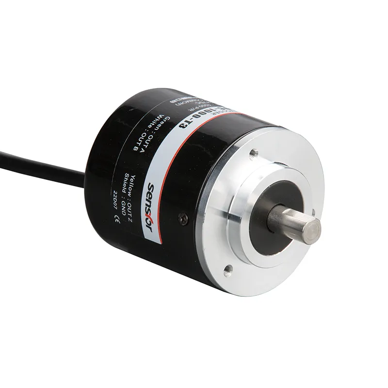
The GOS50C incremental rotary encoder is built for robust performance in heavy-duty industrial automation applications. Featuring a sturdy 50mm flange diameter with an 8mm solid shaft, this encoder provides precise rotational position and speed feedback with pulse resolutions ranging up to 5000 PPR. Designed with enhanced protection against dust and moderate moisture, the GOS50C is ideal for environments with challenging operating conditions. Its multiple output formats, including push-pull and open collector, offer flexible integration with Siemens PLCs and other automation control systems.
الميزات الرئيسية
Incremental rotary encoder with resolution options from 10 to 5000 pulses per revolution
Sturdy 50mm flange housing for reliable mounting stability
8mm solid shaft designed for heavy-duty rotary equipment
Supports output signals: push-pull, open collector, and line driver types
Wide supply voltage range of 5V to 30V DC for versatile system compatibility
Dust-resistant enclosure suitable for industrial factory floors
Precise phase difference outputs (A, B, Z signals and their complements) for accurate position detection
Designed to withstand high shaft shock and vibration loads
مزايا المنتج
Robust mechanical construction suited for continuous industrial use
Versatile resolution and output options allow custom configuration for multiple applications
Compatible with Siemens PLCs and other major industrial control systems
High tolerance to mechanical shock and vibration reduces breakdown risks
Reliable signal output ensures precise control and monitoring of motors, conveyors, and coiling equipment
Easy to install with straightforward wiring and connection
نموذج المنتج والمعنى
| G | 0 | S | 50 | □ | C | 1000 | T | 3 | 2M | |||
| فئة المنتج | نوع المنتج | شكل العمود الرئيسي | محيط المنتج | حجم الرئيسي العمود، فتحة العمود
| المخرج و نموذج الختم | القرار | نموذج الإخراج | إشارة الإخراج | الكابل | |||
| G:incremental type | س:ميجنيتو- الكهرباء L: photoelec– تريسيتي | S:solid shaft | 50:φ50 مم | □ □: Φ8 مم
| C:rear-outlet rubber | 10,20,50, 60,100, 200,360, 400,500, 600,800, 1000,1024,1 200,2000,20 48,2500,300 0,3600,4096
| T: push pull output L: 5V drive output A: 24V drive output | 1: المرحلة 1: مرحلة الإشارة 2:المرحلة AB إشارة 3:إشارة ABZ الطورية 4:مرحلة ABA/B/إشارة 4:4 5:المرحلة ABZA/B/Z/إشارة ABZA/B/Z/ | افتراضي 2m line,For non 2m, labeling is sufficient |
جدول الأسلاك
| لون الخط | Toutput signal | لون الخط | L/A output signal | |
| أحمر | VCC | أحمر | VCC | |
| أسود | GND | |||
| أسود | GND | |||
| أخضر | المرحلة أ | |||
| أخضر | المرحلة أ | أبيض | المرحلة ب | |
| أصفر | المرحلة Z | |||
| أبيض | المرحلة ب | |||
| blue black | أفيس | |||
| أصفر | المرحلة Z | white black | بفاس | |
| yellow black | زفيز | |||
| الدرع | واو - زاي | |||
| الدرع | واو - زاي |
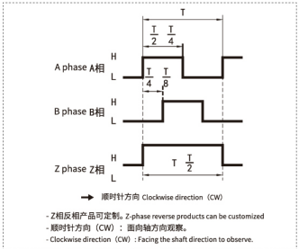
فرق طور الإخراج
الإخراج التكميلي/السحب التكميلي خرج الدائرة المفتوحة الخرج/مجمِّع PN/دائرة مفتوحة الخرج
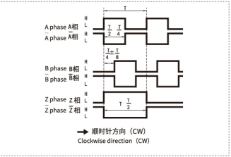
مخرجات محرك الخط الطويل
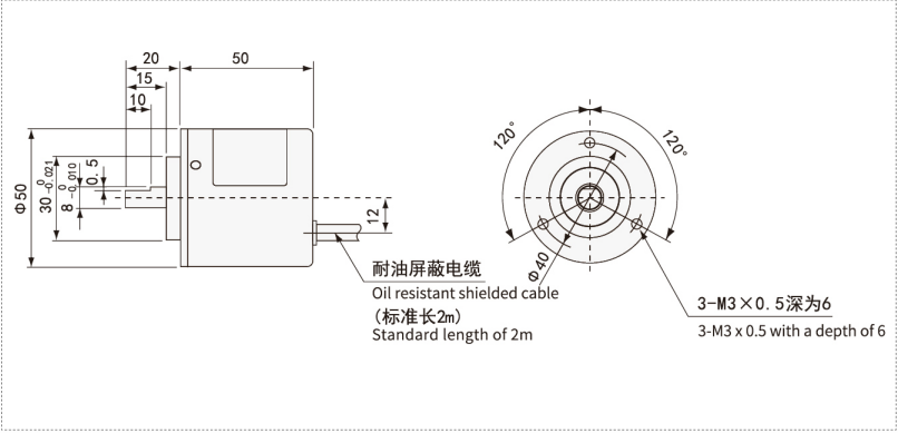
الرسومات الميكانيكية (مم)
سيناريوهات التطبيق
Heavy-duty coiling and rolling machines requiring accurate speed and position control
Conveyor belt systems in manufacturing plants with PLC automation
Industrial motor feedback for precise speed regulation
Automation systems utilizing Siemens PLCs and similar controllers
Packaging machines and material handling equipment
Robotics and mechanical handling applications requiring reliable rotary position feedback
التركيب والصيانة
Verify that the mounting flange and 8mm shaft match the intended application equipment.
Carefully align the encoder shaft to prevent mechanical stress and premature wear; use flexible couplings if necessary.
Securely fasten the encoder with mounting screws to minimize vibrations.
Connect power supply (5-30V DC) observing polarity and follow wiring diagrams for the chosen output signals.
Employ shielded cables for output signals to avoid electromagnetic interference in industrial environments.
Regularly check for dust accumulation and clean the encoder surface gently as needed.
Periodically inspect wiring connections to avoid loose contacts.
Replace the encoder if abnormal signal behavior or mechanical damage occurs.