Types of Modular Contactors: A Practical Selection Guide
Types of modular contactors explained: poles, AC-7a vs AC-7b duty, NO vs NC contact forms, latching types and coil options, with an application-to-type selection matrix.
Read More
If you have ever opened a contactor enclosure and wondered why the power terminals are labelled L1, L2, T1 and T2, you are not alone. These markings are the IEC/EN wiring convention for contactors, and reading them correctly is the difference between a motor that starts cleanly and a control circuit that trips, hums, or fails under load. This guide explains exactly what L1/L2 and T1/T2 mean, how they relate to single-phase and three-phase wiring, where the coil terminals and auxiliary contacts fit in, and the wiring mistakes that damage contactors most often.
The letters on a contactor terminal are not random. In the IEC scheme used on virtually every AC contactor sold outside North America, L stands for “line” (the incoming supply) and T stands for “load” (the outgoing motor or heater). The numbers simply identify each pole: L1/L2 on the input side pair with T1/T2 on the output side.
Think of each L–T pair as a single switch contact inside the contactor. When the coil energises, all pairs close together; when the coil drops out, they all open together. That is what makes a contactor a multi-pole switch rather than a relay with one contact.
In a single-phase application, such as a compressor, a water pump, or a resistive heater, a two-pole contactor uses all four main terminals:
| Terminal | Connected to | Role |
|---|---|---|
| L1 | Live / Phase (e.g. brown) | Incoming supply |
| L2 | Neutral (e.g. blue) or second phase | Incoming supply |
| T1 | Load live terminal | Switched output from L1 |
| T2 | Load neutral terminal | Switched output from L2 |
Wiring L1→T1 and L2→T2 straight through keeps the phase sequence clear and makes future troubleshooting far easier. If you reverse them on one pole only, the contactor still switches, but a downstream device may see swapped live/neutral, which is dangerous on some equipment.
On a three-pole contactor the same convention extends to a third pair, but manufacturers print the terminals slightly differently. Instead of repeating L3/T3, most three-phase contactors label the full set as L1, L2, L3 on the line side and T1, T2, T3 on the load side. The Excel row for this article is wired to a CJX2 three-phase AC contactor, which follows exactly this pattern.
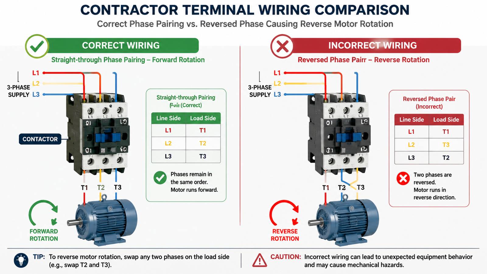
For a three-phase motor, the goal is to preserve phase rotation through the contactor. Whatever order the three phases enter at L1/L2/L3 must come out in the same order at T1/T2/T3. Swapping any two phases anywhere in the circuit reverses the motor direction, which is a classic cause of a “new installation runs backwards” complaint.
Note that in NEMA-marked contactors sold mainly in North America, you may instead see L1/L2/L3 on the line side and T1/T2/T3 on the load side too — the same idea — or older units that print only “L1 L2 L3 / T1 T2 T3” with no separate legend. Either way, line-in/load-out is the rule.
The L/T markings describe only the power path. A contactor has two other terminal groups you will meet when wiring the control circuit:
A1 and A2 are the energising coil terminals. The control voltage (24 V AC/DC, 110 V, 220 V, 380 V — check the coil code printed on the contactor) is applied across A1 and A2. This is the pair your PLC output, thermostat, pressure switch, or push button controls. If the coil voltage is wrong or the coil burns out, the contactor will not pull in no matter what you do at L1/T1.
Auxiliary contacts are small signal contacts mounted on the side of the contactor. Their terminal numbers follow a fixed rule: odd numbers are the common (COM) side, even numbers are the switched side, and the last digit tells you the function:
These aux contacts are how a contactor “tells” the rest of the machine whether it is actually closed — the basis of seal-in circuits and contactor-vs-relay control logic.
Before you wire anything, read the terminal markings printed on the contactor body or in the datasheet, because layout differs between manufacturers and frame sizes. The internal arrangement behind those markings is explained in our guide to AC contactor components; the drawing below shows where each group of terminals sits on a standard frame.
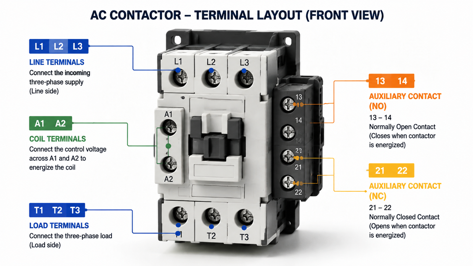
Some contactors integrate the aux block and label the pairs on the side cover. Others (especially compact modular units) squeeze A1/A2 and the aux terminals onto the front face with L1/L2/T1/T2. When in doubt, use a multimeter in continuity mode to confirm which terminals are mechanically linked before energising — the method is covered in our AC contactor testing guide.
Most contactor failures traced back to wiring are not component failures at all. They are one of these four errors:
Feeding power into T1/T2 instead of L1/L2 works mechanically but is poor practice: the load side of the contacts is now permanently live even when the contactor is open, which is a shock hazard for anyone working downstream. Always land the supply on the line side.
On three-phase motor circuits, a single swapped phase between input and output reverses rotation. It does no immediate damage but can wreck a machine that must run one direction only. Check all three poles line-up before closing the circuit.
Tapping the control circuit from the power side without checking voltage ratings is a common source of burned A1/A2 coils. The coil must see exactly its rated control voltage. Deriving 220 V coil feed from a 380 V line is a sure way to smoke the coil on the first pull-in.
Spreading a three-phase load across fewer poles, or daisy-chaining two loads off one T terminal, overworks a single contact set. The rating stamped on the contactor applies per pole, and a current imbalance accelerates contact erosion. If you need more capacity, select a larger frame — see how to size a contactor for the AC-3/AC-1 rules.
A five-minute continuity check prevents most first-power-up problems:
If a pair reads open when it should be closed, or closed when it should be open, stop and re-check the wiring — the fault is almost always upstream, not in the contactor itself.
L1, L2, T1 and T2 are simply the line-in and load-out markings of a contactor’s power contacts: L is the incoming supply, T is the switched output to the load, and each numbered pair is one pole. Read them in order, keep the phase sequence straight, respect the A1/A2 coil and auxiliary terminal conventions, and most contactor wiring problems disappear before they start. When you are selecting a contactor for a new build or a replacement, start from a model whose terminal layout and markings match your wiring plan — our CJX2 series three-phase AC contactors follow the standard L1/L2/L3 → T1/T2/T3 arrangement and are available from 9 A to 95 A for common motor applications.
For a single-phase load that is polarity-sensitive (electronics, some control transformers), yes. For a pure resistive load such as a heater, no. When in doubt, keep L1 (live) and L2 (neutral) consistently paired with T1 and T2.
T stands for “load” (the French term “tête” is sometimes cited historically, but the practical meaning is the switched output side). T1 is the load terminal switched from L1; T2 is the load terminal switched from L2.
No. L terminals are the incoming line side; T terminals are the outgoing load side. They are electrically connected only when the contactor is energised and the contacts are closed.
Yes. In single-phase wiring, L1 takes the live conductor and L2 commonly takes the neutral, with T1 and T2 feeding the load. This is the standard arrangement for a two-pole contactor switching a single-phase circuit.
The coil connects to A1 and A2. Never connect the coil across the L/T power terminals unless the coil voltage rating matches the supply voltage exactly.
Two phases are swapped somewhere between the supply, the contactor, and the motor. Check that the phase order entering L1/L2/L3 exits the same order at T1/T2/T3, then verify the motor terminals.