BRM8-15kA Type 1 Surge Protector at the Service Entrance
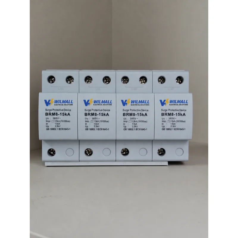
Some surge events arrive with so much energy that no downstream device can survive them. That is the case at the origin of an installation, where a lightning strike on the building or on the overhead supply can drive part of its current straight into the incoming conductors. The BRM8-15kA is a Type 1 surge protector placed at exactly that boundary, sized to take the hit so that everything behind it does not have to.
The device is a four-pole unit for 385 V systems with an impulse discharge current of 15 kA on a 10/350 µs waveform, a nominal discharge current of 15 kA and a voltage protection level of 2.5 kV.
What a 10/350 Waveform Actually Demands
Surge currents are described by how fast they rise and how long they last, and the two standard shapes describe very different physical events. An 8/20 µs impulse rises in eight microseconds and is effectively over in twenty. A 10/350 µs impulse rises in ten microseconds and then keeps flowing for three hundred and fifty — a far longer delivery of energy for a comparable peak value.
That longer tail is what separates a Type 1 device from a Type 2 device. A varistor that shrugs off a 20 kA impulse of the 8/20 shape can be destroyed by a 15 kA impulse of the 10/350 shape, because the integral of energy under the curve is far larger. Selecting a Type 1 surge protector by peak current alone, without checking the waveform it was rated on, is the single most common way to under-specify an entrance position.
Reading Iimp 15 kA Correctly
Iimp is the impulse current rating, and it is always quoted against a waveform. Here it is 15 kA at 10/350 µs, which is a genuine direct-strike class rating rather than a stretched 8/20 figure. The nominal discharge current of 15 kA refers to the repetitive 8/20 tests that establish service life. Having both numbers on the label means the device has been characterised for the single big event and for the many smaller ones, which are two different questions.
The 2.5 kV protection level is the residual voltage that appears across the terminals during conduction. Compare that figure against the impulse withstand of the equipment in the board, not against the nominal supply voltage, because it is the equipment’s tolerance that determines whether the residual is acceptable.
Construction That Survives the First Event
High-energy varistor discs
The discs in a Type 1 device are physically larger and more numerous than those in a Type 2 module of similar footprint. The extra mass is what absorbs the long tail of a 10/350 impulse without the disc cracking under thermal shock. There is no way to obtain that capability by stacking small discs inside the same 18 mm width; the housing has to give the mass somewhere to sit.
An arc chamber that does not rely on a zero crossing
If a varistor is driven into failure, the resulting current is a power-frequency arc that, on an AC supply, would normally extinguish at the next zero crossing. Inside a confined module the arc can restrike instead, which is why the disconnection mechanism has to physically separate the contacts rather than wait for the voltage to pass through zero. The sealed chamber and the guided contact travel are there to make that separation reliable and to keep the arc products inside the housing.
Terminals sized for the cable the board actually uses
Conductors from 6 to 25 mm² are accepted, which covers the range normally run to a main distribution board. The earth terminal is deliberately the same size as the line terminals, because a protective conductor smaller than the line conductor adds impedance precisely where the surge needs the least resistance.
Four Poles at the Origin
At the entrance position the four-pole arrangement protects each phase and the neutral independently, so a surge arriving on one phase is diverted without depending on the other poles or on the quality of the neutral bond. In a TT system this matters even more than in TN-S, because the neutral is not bonded to earth at the installation and cannot be assumed to be at earth potential during an event.
The Type 1 surge protector is intended for installation on a 35 mm DIN rail in the main distribution board, at the point where the incoming supply enters the building. Ambient range is −40 to +80 °C and the enclosure is IP20, so it belongs inside a closed enclosure rather than in an external cabinet.
Coordinating With a Second Stage
A Type 1 surge protector limits the surge to a level that a downstream device can then handle, but it rarely brings the residual low enough for sensitive electronics on its own. The usual arrangement is this unit at the main board and a Type 2 module at each sub-board, with the cable between them providing the impedance that lets the two stages share the work. Fitting the second stage is not optional if the goal is to protect control electronics rather than just to protect the building wiring.
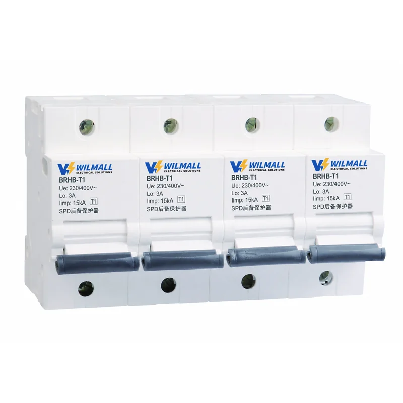
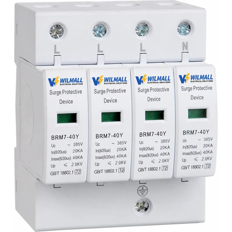
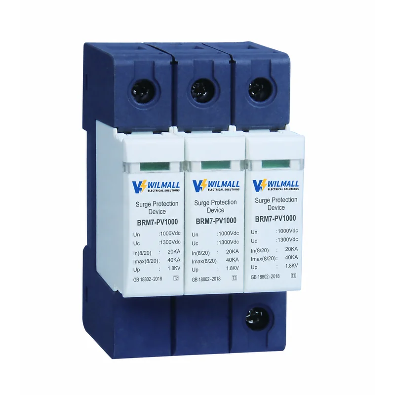
The matching second-stage device in this range is the BRM7-40Y Type 2 module. Both stages need a short-circuit protective device ahead of them that will not trip on the impulse itself, which is the job of the BRHB backup protector. Where the same site also has a photovoltaic array, the BRM7-PV1000 direct current device covers the string side separately, because the two systems have different fault behaviour and must not share a protective device.
Evidence to Ask For Before a Tender
Buyers specifying a Type 1 surge protector for a tender usually need documentation rather than a catalogue page. Ask for the test report covering the 10/350 impulse current, the declaration of conformity for the standard the device is marked against, and the dimensions drawing for the board layout. Those three documents answer the questions an engineer will raise, and they are available for this range on request.
Ordering for Projects
Every Type 1 surge protector in this range is assembled and tested in our own plant and can be marked with a distributor’s brand for volume quantities. Because the front cover is printed in-house, a private-label batch does not pass through a third party between test and packing. Send the board rating, the earthing arrangement and the quantity per site, and the model, marking and delivery schedule are settled in the same reply.
For BRM8-15kA price, test reports, dimensions drawing or OEM supply terms, contact our sales team with the project details.
PREGUNTAS FRECUENTES
What does Iimp 15 kA at 10/350 µs mean in practice?
It is the impulse the device will pass in a single event with the long-tail waveform that a direct strike produces. The 10/350 shape delivers far more energy than an 8/20 pulse of the same peak, so the figure is not comparable with the Imax rating of a downstream module.
Where exactly should this device be installed?
At the origin of the installation, on the incoming side of the main distribution board, at the boundary between the unprotected zone and the protected zone. It is the first device in the chain and it takes the largest share of the energy.
Does a Type 1 device remove the need for a Type 2 stage?
No. The entrance device brings the surge down to a level that a second stage can handle, but the residual at the sub-board is still higher than sensitive electronics will tolerate. A Type 2 module at each sub-board is what finishes the job.
Does it need a backup protector ahead of it?
Yes. A short-circuit protective device is required, and it has to be one that will not operate on the impulse itself. The BRHB range is made for that position, and the T1 version is the companion for this device.
Can it be used in a TT system?
Yes. The four-pole arrangement protects each phase and the neutral independently, which matters more in a TT system because the neutral is not bonded to earth at the installation and cannot be assumed to sit at earth potential during an event.
Which documents come with a tender order?
The test report covering the 10/350 impulse current, the declaration of conformity for the standard the device is marked against, and the dimensions drawing for the board layout. All three are available on request with the quotation.
Request Quote
Tell us your specifications, quantity, or application scenario and we will reply with a tailored quote.