Quick answer: In a standard star-delta starter the three contactors do not carry the same current. The main and delta contactors carry winding current, which is 58% of motor FLC (FLC ÷ √3); the star contactor carries roughly 33% (FLC ÷ 3) and only during the start. The overload relay goes in the winding circuit and is set to 58% of FLC. One exception matters: if the delta contactor is fed from the load side of the main contactor instead of the supply side, the main carries full line current and must be sized at 100% of FLC.
Star-delta is the cheapest way to cut a motor’s starting current, and the most commonly mis-sized starter in a panel shop. Three contactors, one overload relay and a timer are all it takes, so it gets treated as a wiring exercise. It is not — it is a current-distribution exercise, and the distribution is not obvious from the schematic.
The failure signatures are consistent. A main contactor sized like a direct-on-line starter, running at 40 °C over a third of its rating and costing more than it needed to. A star contactor picked from the same frame as the other two, wasting space and money. An overload relay dialled to the nameplate current while sitting in the winding circuit, so it protects nothing and trips constantly. Or the two changeover contactors closing together once, which is a phase-to-phase short and the end of the starter.
This page covers what star-delta does to current and torque, why the three contactors divide the current the way they do, the topology exception that changes the main contactor’s rating, a worked sizing example, and the wiring details that decide whether the starter survives commissioning. For the frame range itself, start at the AC contactor category.
What star-delta actually does to the motor
Star-delta needs a motor with six terminals that is designed to run in delta at the supply voltage — a 400 V Δ / 690 V Y machine on a 400 V supply. A motor marked 690 V Δ / 400 V Y is not suitable: it is meant to sit in star permanently at 400 V.
During the start the windings are connected in star, so each winding sees the phase voltage, which is 58% of line voltage. Winding impedance is essentially unchanged in that instant, so winding current drops by the same 1.732 factor. Line current drops further, because in star the line current equals the winding current, whereas in delta the line current is 1.732 times the winding current. The two factors compound:
- Starting line current falls to about one third of the direct-on-line value. A motor with 6 × FLC locked-rotor current draws roughly 2 × FLC in star.
- Starting torque falls to about one third as well, because torque follows the square of the applied voltage.
That second line is the constraint. Star-delta suits centrifugal pumps and fans started against a closed valve or damper, unloaded compressors, and lightly loaded conveyors. It does not suit a load that needs breakaway torque — a loaded positive-displacement pump, a fully loaded conveyor, a crusher — because one third of DOL torque may not be enough to accelerate at all. A motor that cannot reach speed in star sits on high slip, draws more current than intended, and trips the overload before the timer ever changes over.
Why the three contactors divide the current
In delta run, each winding sits across the full line voltage, and each winding current is the line current divided by √3 — about 0.577 of FLC. The star contactor is different: it only closes during the start, when the winding voltage is 1/√3 of line, so the current it carries is about one third of the direct-on-line starting current.
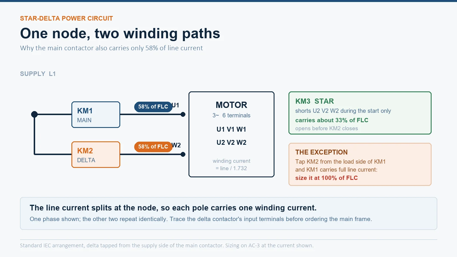
The part that surprises people is that in the standard arrangement the main contactor also carries only winding current. That is because the delta contactor taps its supply from the line side of the main contactor. At each phase node the current splits into two paths: one through the main contactor into the start of a winding, one through the delta contactor into the end of another winding. Each path carries one winding current, so each pole of the main contactor carries 0.577 of line current, not the full line current.
| Componente | Current it carries | Typical rating (AC-3) | Notes |
|---|---|---|---|
| Main contactor (KM1) | Winding current, start and run | 58% of FLC | 100% of FLC if delta taps the load side of KM1 |
| Delta contactor (KM2) | Winding current, run only | 58% of FLC | Closed for the whole run period |
| Star contactor (KM3) | Star winding current, start only | 33% of FLC | Short duty; some makers use the delta frame for long starts |
| Thermal overload relay | Winding current | Set to 58% of FLC | Set to 100% of FLC only if mounted in the supply line |
| Six motor leads | Winding current | 58% of FLC | Supply cable stays at 100% |
The topology exception that changes everything
Published guides disagree on whether the main contactor is 58% or 100% of FLC, and both are right for the arrangement they assume. It is worth understanding which one you are building before you order.
Delta tapped from the supply side of the main contactor — the classic IEC panel, and the arrangement the standard selection tables assume. Line current splits at each node between the main and delta paths, so the main carries winding current and can be sized at 58%. This is also the arrangement that keeps the delta contactor’s input terminals live when the starter is off, which is a maintenance consideration worth knowing.
Delta tapped from the load side of the main contactor — the main contactor then sits in the line ahead of the split and carries full line current, so it must be sized at 100% of FLC. This arrangement adds no operating benefit and costs a frame size, which is why it is uncommon, but it does exist in rebuilt panels and in some imported starters. Verify by tracing the delta contactor’s input terminals back to the line side of the main contactor.
There is a third variant worth recognising: starters with no main contactor at all, where the supply is permanently landed on the motor through a disconnect and only the star and delta contactors switch. These are cheaper and reduce component count, but they leave the motor terminals live whenever the starter is isolated only at the star contactor, and they do not provide a load-breaking means of disconnection. If you are replacing a starter, check which variant you are replacing.
Worked example: 30 kW at 400 V
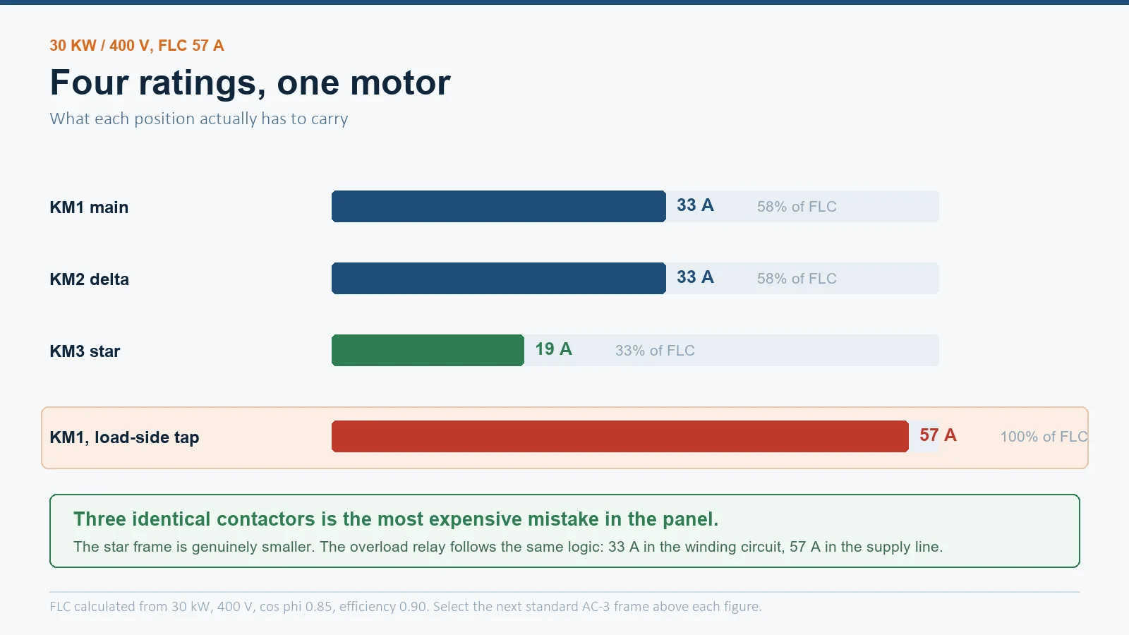
A 30 kW, 400 V, 50 Hz motor with cos φ 0.85 and efficiency 0.90 draws roughly 57 A at full load. Applying the multipliers:
| Position | Calculation | Current | Selection |
|---|---|---|---|
| Main contactor (KM1) | 57 × 0.577 | 33 A | 40 A AC-3 frame |
| Delta contactor (KM2) | 57 × 0.577 | 33 A | 40 A AC-3 frame |
| Star contactor (KM3) | 57 × 0.33 | 19 A | 25 A AC-3 frame |
| Overload relay, winding circuit | 57 × 0.577 | 33 A | Relay range spanning 33 A |
| Overload relay, supply line | 57 × 1.0 | 57 A | Relay range spanning 57 A |
Two details in that table are worth more than the arithmetic. First, the star contactor is genuinely a smaller frame — using three identical contactors is the single most common way to overspend on a star-delta panel. Second, the overload relay figure changes with its position, and the position is a design choice you have to make deliberately.
Overload relay position decides its setting
The relay must protect the motor windings. Where it sits determines what it measures.
- In the winding circuit — between the main contactor output and the motor terminals. It sees winding current in both star and delta, so the dial goes to 0.577 × FLC. This is the usual arrangement, and it lets a smaller, cheaper relay be used.
- In the supply line — ahead of the starter. It sees full line current, so the dial goes to FLC.
Setting a winding-circuit relay to nameplate FLC is the classic error. The relay then needs 1.73 times the winding current to trip, so a genuine overload runs the windings hot long before protection operates. The opposite error — setting a supply-line relay to 0.58 × FLC — causes nuisance trips at normal load.
Trip class matters on long starts. A Class 10 relay trips in about 10 seconds at six times its setting, which suits a star-delta start because the starting current is already reduced. For high-inertia fans or loaded conveyors where the star phase runs long, a Class 20 or 30 relay avoids tripping on a start that is simply slow. The trade-off between class, ambient temperature and nuisance tripping is covered in 3-phase motor starter overload protection sizing.
The wiring details that decide whether it survives
Star-delta fails at commissioning more often than in service. Four checks cover most of it.
Interlocking. The star and delta contactors must never close together — that is a direct phase-to-phase short through the windings. Electrical interlock through the auxiliary NC contacts is the minimum; a mechanical interlock between the two contactors is the standard for anything that matters, because a welded auxiliary contact can defeat an electrical interlock alone. The same principle governs any reversing pair, covered in reversing contactor wiring.
Dead time at changeover. Standard starters use open transition: the star contactor opens, there is a pause of typically 50 to 100 ms for the field to collapse and the arc to extinguish, then the delta contactor closes. Too short and the two overlap; too long and the motor decelerates far enough that closing into delta produces a current spike approaching direct-on-line. The transition is the single most stressful moment in the cycle.
Phase sequence on the delta loop. The delta contactor must cross-connect so that the motor continues in the same direction. Cross it the wrong way and the motor reverses at the transition — a mechanical shock that can shear a shaft coupling and a current spike that can weld the contactor. Verify rotation on the first start before connecting the driven machine.
Terminal links. Six-terminal motors ship with links fitted for a single-voltage connection. Those links must come out before a star-delta starter is connected. A link left in place shorts part of the winding and the starter will not behave as designed.
Setting the timer
The timer should switch to delta when the motor is at roughly 80 to 90% of rated speed. Switching earlier means the motor has not accelerated, so closing into delta produces a second inrush close to direct-on-line. Switching later means the motor runs in star under load, at high slip, drawing more current than it should and heating.
Starting points by size, for pumps and fans: 5 to 7 seconds up to about 30 kW, 7 to 12 seconds for 30 to 110 kW, and 8 to 15 seconds for compressors with an unloaded start. Treat those as starting values and tune on site: clamp the line current during the star phase and watch for the point where it stops falling, which is where the motor has stopped accelerating.
When star-delta is the wrong starter
Star-delta reduces current by reducing voltage, and it reduces torque by the same proportion. That single fact rules it out wherever the load needs torque at zero speed.
If the load cannot break away in star, the alternatives are a soft starter — which ramps voltage continuously and can be tuned to the load — or a variable frequency drive, which controls torque directly. Both cost more than three contactors. If a soft starter is fitted, the bypass contactor question becomes the one that decides panel life, covered in bypass contactor and soft starters.
Two more selection points apply whichever starter you choose. Contactors in a hot panel need derating, not the catalogue figure — see contactor derating for temperature, altitude and dust. And a star-delta starter that is switched frequently is a duty-cycle problem, not a frame-size problem.
Mistakes worth checking before you close the panel
| Mistake | What happens | Fix |
|---|---|---|
| Three identical contactors | Oversized star frame, wasted cost and space | Star at 33% of FLC, main and delta at 58% |
| Main sized at 58% when delta taps the load side | Main contactor runs hot, short life | Trace the delta supply; use 100% for a load-side tap |
| Overload set to nameplate FLC in the winding circuit | No effective winding protection | Set to 0.577 × FLC in the winding circuit |
| Electrical interlock only | One welded auxiliary contact produces a short | Add a mechanical interlock between star and delta |
| Timer too short | Second inrush at changeover, breaker trips | Set for 80 to 90% speed, tune on site |
| Delta loop cross-connected the wrong way | Motor reverses at transition | Verify rotation on first start before coupling the load |
| Motor terminal links left fitted | Winding partially shorted, wrong currents | Remove links before connecting the starter |
PERGUNTAS FREQUENTES
Why are the main and delta contactors sized at 58% of motor FLC?
Because in the standard arrangement both are in series with motor windings rather than with the supply line. In delta the winding current is the line current divided by √3, which is 0.577. They are selected on their AC-3 rating at that current.
Why is the star contactor smaller than the other two?
It only carries current during the star phase, when each winding sees 1/√3 of line voltage and the line current is about one third of the direct-on-line starting current. Sizing at roughly 33% of FLC is the usual rule. For long or frequent starts, some manufacturers recommend using the same frame as the delta contactor instead.
What should the overload relay be set to in a star-delta starter?
If the relay is in the winding circuit, between the main contactor and the motor, set it to 0.577 × nameplate FLC. If it is in the supply line ahead of the starter, set it to the full nameplate FLC. Getting this backwards either removes protection or causes nuisance trips.
Can a star-delta starter be used on a single-phase motor?
No. It works by switching a three-phase winding between two configurations and needs six accessible terminals. Single-phase motors use capacitor or other reduced-voltage starting methods.
How much does star-delta reduce starting current?
Starting line current and starting torque both fall to about one third of their direct-on-line values. A motor with 6 × FLC locked-rotor current draws roughly 2 × FLC in star, plus a short peak at the changeover to delta if the transition is mistimed.
Does the motor need a special winding for star-delta?
It needs six terminals and a delta rating that matches the supply voltage — for example 400 V delta on a 400 V supply. A motor wound for 690 V delta cannot be star-delta started on 400 V, because it is designed to run permanently in star at that voltage.
What to do next
Before ordering, confirm four things: the motor is delta-rated at the site voltage with six terminals, whether the delta contactor taps the supply side or the load side of the main, where the overload relay will sit, and the real run-up time of the driven load. Those four answers fix every current in the panel.
For the main and delta positions, the CJX2 series three-phase contactor covers the AC-3 ratings these positions need, and the CJX2-D (LC1-D) range covers the smaller frames down to a few kilowatts. For the winding-circuit relay, the CR2 thermal overload relay from 0.1 A to 630 A spans the 58% settings that star-delta starters actually use. Send the motor nameplate, the starter topology and the starts per hour, and we will confirm the three frames against your numbers.