What Is a Contactor? How It Works, Parts, Types & Uses
Published: Author: Lisa
A contactor
is an electrically controlled switch used to make and break power circuits under normal operating conditions. Unlike the manual switches found in homes, contactors are built for repeated on/off cycling, high current loads, and remote or automatic control. You will find them in motor starters, heating systems, lighting banks, capacitor banks, and power distribution panels.
This guide explains how a contactor works, what its main parts do, the common types you will encounter, and where each type is used. It also covers the practical differences between AC and DC contactors, the key ratings that matter when you choose one, and a quick FAQ section for buyers and maintenance teams.
What Is a Contactor?
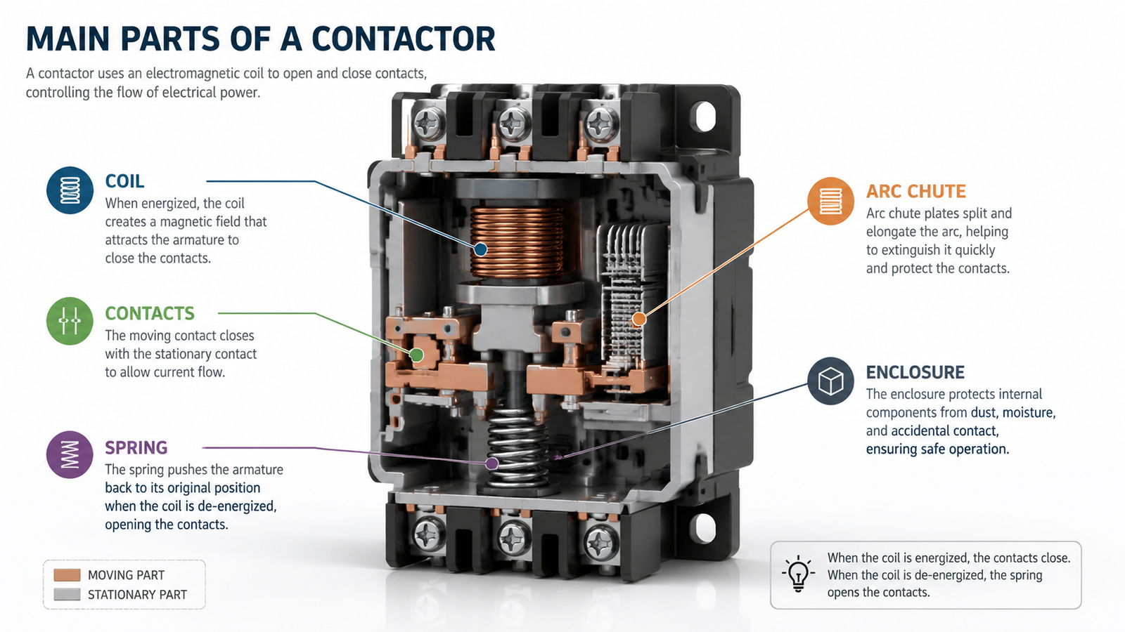
A contactor is a heavy-duty relay. It opens and closes an electrical circuit by moving a set of power contacts with an electromagnetic coil. When the coil is energized, it creates a magnetic field that pulls a movable armature toward a fixed core. This action closes the main contacts and allows current to flow to the load. When the coil is de-energized, a spring returns the armature to its original position and the contacts open.
Contactors are normally held open or closed by springs and are not intended to interrupt short-circuit currents. For fault protection, a separate circuit breaker or fuse must be installed upstream. The contactor’s job is reliable, frequent switching under load.
How a Contactor Works
The working principle is straightforward. A low-power control voltage is applied to the coil. The coil becomes an electromagnet and pulls in the armature. The armature pushes or pulls the moving contacts so they mate with the fixed contacts. Once closed, the main power path is complete.
Coil energization — The control circuit supplies voltage to the coil.
Magnetic attraction — The coil generates a magnetic field strong enough to overcome the contact spring force.
Contact closure — The moving contacts close against the fixed contacts and the load receives power.
Hold-in state — The coil stays energized and the contacts remain closed.
Drop-out — When the control signal is removed, the spring opens the contacts and the load is disconnected.
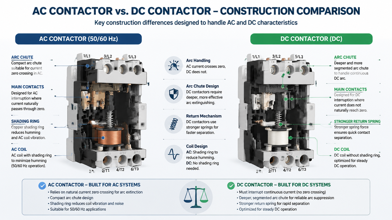
In AC contactors, a shading ring prevents the contacts from chattering every time the alternating current crosses zero. In DC contactors, the coil current is steady, so shading rings are not required, but the coil must be sized for continuous DC heating.
Main Parts of a Contactor
Knowing the parts helps when you read datasheets, order spares, or troubleshoot a starter that keeps dropping out. The main components are:
Electromagnetic coil — The solenoid winding that creates the magnetic field. Coils are rated for a specific control voltage and frequency.
Fixed and moving contacts — The current-carrying surfaces. Main contacts carry the load current; auxiliary contacts carry small signal currents for interlocks and indication.
Arc chute / arc suppression — Channels or plates that stretch and cool the arc formed when contacts open under load.
Spring mechanism — Returns the contacts to the open position when the coil is de-energized and provides contact pressure.
Шкаф — Insulates and protects the internal parts from dust, moisture, and accidental contact.
Common Types of Contactors
Contactors are grouped by coil supply, pole count, utilization category, and mounting style. The table below summarizes the most common types and where they fit.
Тип
Key characteristic
Typical uses
AC contactor
Coil powered by alternating current; uses shading ring
Induction motors, HVAC compressors, pumps, fans
DC contactor
Coil powered by direct current; no shading ring
Battery systems, EV charging, solar inverters, DC traction
Interlocked pair for forward/reverse motor control
Hoists, conveyors, machine tools
Pole count is another practical divider. A 3-pole contactor is the default for three-phase motors. A 4-pole version adds a neutral or auxiliary switched circuit. Single- and 2-pole contactors are common in lighting and heating circuits.
Where Contactors Are Used
Contactors turn up anywhere a load needs frequent or remote switching. Common applications include:
Motor control — DOL, star-delta, and reversing motor starters.
HVAC and refrigeration — Compressors, condenser fans, and electric heaters.
Lighting — Banks of high-bay, street, or emergency lights switched together.
Capacitor banks — Power-factor correction and harmonic filtering equipment.
Industrial heating — Electric furnaces, ovens, and drying equipment.
Renewable energy — DC-link switching in solar and battery systems.
AC vs. DC Contactors: What Changes?
The coil supply changes the contactor’s internal design and behavior. AC contactors rely on a shading ring to keep the armature pulled in during the zero-crossing of the sine wave. They also tend to be smaller and less expensive for the same current rating because AC arcs extinguish naturally at each half-cycle.
DC contactors must break a steady arc, so they need stronger arc-suppression features, wider contact gaps, or magnetic blowout coils. DC coils also run hotter because there is no inductive reactance to limit current. Swapping an AC coil for a DC coil in the same frame is not safe unless the manufacturer explicitly allows it.
Key Ratings When Choosing a Contactor
Selecting the right contactor is more than matching current and voltage. The ratings that matter are:
Rated operational current (Ie) — The current the contactor can carry and switch under specified conditions.
Rated insulation voltage (Ui) — The maximum voltage the contactor insulation can withstand continuously.
Utilization category — AC-1 for resistive loads, AC-3 for cage motors under normal start/stop, AC-4 for inching/plugging.
Coil voltage — The control-circuit voltage that operates the coil; must match your panel supply.
Mechanical and electrical life — Number of no-load operations and rated-load operations before contact replacement.
Short-circuit coordination — The contactor must be protected by a compatible fuse or breaker type.
If you need a contactor for a 225 A motor circuit, a heavy-duty AC unit such as the CJX2-F225 3-pole AC contactor covers common 380 V–660 V three-phase applications. Always confirm the utilization category and coil voltage against your panel design.
Заключение
A contactor is the workhorse that turns electrical loads on and off under automatic or remote control. Understanding its parts, operating principle, and type differences lets you match the device to the job rather than oversizing or installing the wrong coil voltage. Keep utilization category, pole count, coil supply, and protection coordination in mind, and the contactor will deliver reliable switching over a long service life.
They share the same electromagnetic switching principle, but contactors are built for higher power and repeated duty. Relays typically switch low-current control signals, while contactors switch motor and heater loads.
Can a contactor protect against short circuits?
No. A contactor is not a protective device. It must be paired with a fuse or circuit breaker sized to clear short-circuit and overload faults.
What happens if the coil voltage is wrong?
Undervoltage causes weak pull-in, chatter, and burnt contacts. Overvoltage overheats and eventually burns out the coil. Always match the coil rating to the control-circuit supply.
How do I know if a contactor is AC or DC?
Check the coil marking on the nameplate or the prefix on the order code. AC coils are often marked with a voltage and frequency such as “220 V 50/60 Hz.” DC coils show a voltage without a frequency, such as “24 V DC.”
Why does my contactor buzz?
Buzzing usually comes from a failing shading ring, a cracked pole face, low coil voltage, or dirt on the magnet surfaces. Inspect the pole faces and measure the coil voltage before replacing the unit.
What is a utilization category?
It describes the load and switching duty. AC-1 is for non-inductive or slightly inductive loads. AC-3 covers normal starting and stopping of cage motors. AC-4 is for starting with inching or plugging.
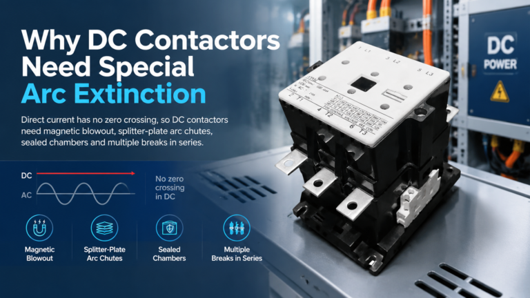
DC contactors need special arc extinction because DC current has no natural zero crossing. See how magnetic blowout, arc chutes and series breaks kill a DC arc — and how to specify one correctly.
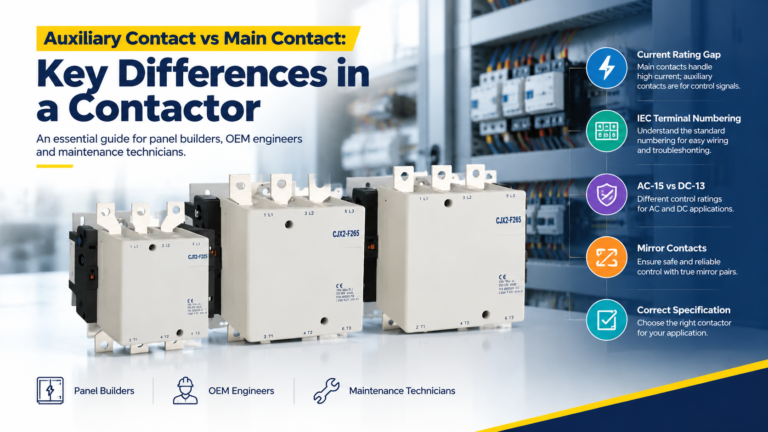
Main contacts carry the motor current; auxiliary contacts carry control signals. Learn the real rating gap, IEC terminal codes, and how to spec both correctly.
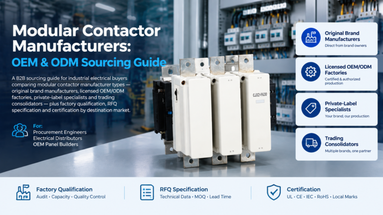
A sourcing guide to modular contactor manufacturers: match the four supplier archetypes, qualify any factory with a nine-point framework, and send an RFQ that gets comparable quotations.