


Description
The 38 Series Incremental Rotary Encoder is a compact and highly reliable sensor designed to provide precise rotational position and speed feedback for automation, CNC machines, robotics, packaging, and other industrial equipment. Integrating advanced optical and mechanical technologies, this rotary encoder generates accurate incremental pulse signals to ensure high-resolution monitoring and control of shaft movement. Its durable construction supports stable operation under demanding environmental conditions, making it an ideal choice for speed regulation, position measurement, and closed-loop feedback systems.
Key Features
Compact Design: Small external diameter of 38mm with various shaft options including solid and hollow shafts for flexibility in installation.
High Resolution: Available in multiple pulse per revolution (PPR) options such as 100, 200, 360, 400, 600, and higher resolutions up to 1024 PPR for precise angular and speed feedback.
Multiple Output Types: Supports open-collector, voltage, and complementary output modes for compatibility with diverse control systems.
Wide Operating Voltage Range: Typically operates on DC 5 to 24V ±10%, suitable for a broad range of industrial environments.
Robust and Reliable: Constructed with durable materials, sealed housing (IP65 or higher options), and designed to withstand shock, vibration, and harsh conditions.
High-frequency Response: Enables accurate real-time measurement even at high rotational speeds (up to 6000 RPM or as specified).
Versatile Applications: Ideal for bending machines, robotics, CNC machining, packaging equipment, food processing, and solar cutting machines.
Product Model And Meaning
| 38 | □ | A | 05 | – | 1000 | – | T | 3 | – | 2M |
| Contour of product | Size of main shaft,shaft hole | Outlet and sealing form | Outline structure | Resolution | Output form | Output signal | Cable | |||
| 38:φ38mm | □:φ6mm (默认 | A:side outlet rubber | 05:5 outline structure5 | 10,20,50, 60,100, 200,360, 400500, 600,800, 1000,1024, 1200,2000, 2048,2500, 3000,3600, 4096 | C: open collector output F:complementary output L:5V drive output A:24V drive outpu | 1:Phase A signal 2: phase AB signal 3:phase ABZ signal 4:phase ABA/B/ signal 6:phase ABZA/B/Z/ signal | Default 2m line,For non 2m, labelingis sufficient |
Wiring Table
| Line color | T output signal | – | Line color | L/A output signal |
| brown | VCC | brown | VCC | |
| blue | GND | |||
| blue | GND | |||
| black | A phase | |||
| black | A phase | white | B phase | |
| orange | Z phase | |||
| white | B phase | |||
| black red | Aphase | |||
| orange | Z phase | white red | Bphase | |
| orange red | Z phase | |||
| shield | F ·G | |||
| shield | F ·G |
Product Parameter
1. Model / Series: GLS38A05
2. Product Type: Incremental Rotational Encoder
3. Function: Speed, position, and direction feedback
4. Applications: Motors, CNC machines, conveyors, robotics, automation systems
Meta Description
Source GLS38A05 Rotational Encoder from a trusted supplier, manufacturer and factory. OEM/ODM custom service at wholesale price.
Product Details
The GLS38A05 Rotational Encoder is an incremental rotary encoder designed to convert shaft rotation into accurate pulse signals for speed, position, and direction feedback. It helps industrial automation systems improve motion control accuracy, equipment stability, and production efficiency.
This rotational encoder is widely used in motors, CNC machines, packaging equipment, conveyors, textile machinery, printing machines, robotics, elevators, and industrial control systems. It is suitable for industrial users, commercial users, electrical contractors, distributors, and bulk procurement buyers.
As a professional Rotational Encoder supplier, manufacturer, wholesaler, distributor, factory, and OEM/ODM partner, we provide stable quality, custom specifications, bulk supply, and competitive wholesale price solutions for B2B projects.
Key features include compact GLS38A05 design, incremental signal output, precise rotation feedback, fast response, easy installation, durable construction, and reliable performance in demanding industrial environments.
Product Advantages
Stable and Accurate Performance: The encoder’s optical sensing technology combined with precise machining ensures low error rates and consistent output signals for enhanced machine accuracy.
Low Power Consumption: Efficient design reduces power usage while maintaining high signal integrity.
Easy Integration: Multiple output signals (A, B, Z phases) and standard interfaces (TTL, HTL, ABZ) facilitate straightforward connection to various PLCs, motion controllers, and microcontrollers.
Flexible Mounting Options: Supports both side-entry cable and connector termination modes with options for different shaft styles and mounting flanges.
Durability Under Extreme Conditions: Resistant to dust, moisture, and mechanical stress; some models offer double-sealed housings for wash-down environments or chemical exposure.
Output Phase Difference
push pull output

longline drive output

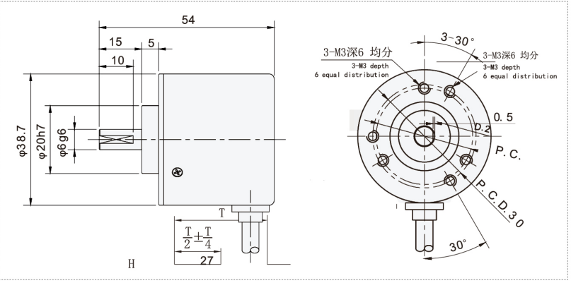
Mechanical Drawings(mm)
Installation and Maintenance
Installation Steps
Preparation: Ensure the machine is powered off before installation. Verify compatibility with system voltage and interface requirements.
Mechanical Mounting: Secure the encoder on the motor or machine shaft using appropriate clamps or adapter kits. Ensure shaft alignment to prevent excessive radial or axial loads.
Electrical Connection: Connect the encoder output wires or connectors to control system inputs, observing correct wiring for output type (e.g., open-collector, voltage output). Shielded cables are recommended to prevent signal noise.
Verification: Power on the system and check output pulses with an oscilloscope or PLC input to confirm proper operation and signal integrity.
Calibration: If required, perform zero-position or reference pulse calibration according to your control system’s manual.
Maintenance Tips
Regularly inspect the mechanical mounting for loosening or shaft wear.
Keep the encoder and connectors clean and dry; avoid opening the encoder housing to prevent contamination.
Verify cable integrity and shield effectiveness annually or as part of routine maintenance.
Avoid electrical modifications to the encoder circuitry to maintain warranty and performance.
Use protective covers or boots in harsh environments to extend service life.
Product Applications
The GLS38A05 Incremental Rotary Encoder is widely used in:
Industrial automation systems for motor speed and position feedback.
Robotics for joint and arm position control.
CNC machining centers to provide precise spindle speed and position data.
Conveyor and packaging systems for speed regulation and product tracking.
Printing and textile machinery synchronization.
Steel mills and rolling mills for controlling roller speed and thickness accuracy.
Automated inspection and assembly lines requiring high-resolution motion feedback.
FAQ
Q1: What is a GLS38A05 Rotational Encoder used for?
It is used for speed measurement, position feedback, direction detection, and motion control in automation systems.
Q2: Are you a Rotational Encoder manufacturer or supplier?
Yes, we are a factory supplier supporting wholesalers, distributors, electrical contractors, and industrial users.
Q3: Can the GLS38A05 Rotational Encoder be customized?
Yes, OEM/ODM and custom options are available for resolution, shaft type, cable length, output signal, voltage, and connector type.
Q4: Do you offer wholesale price for distributors?
Yes, we provide competitive wholesale price options for distributors, wholesalers, and bulk procurement buyers.
Q5: Where can this Rotational Encoder be applied?
It is suitable for motors, CNC machines, conveyors, packaging equipment, robotics, elevators, and industrial automation systems.
Request Quote
Tell us your specifications, quantity, or application scenario and we will reply with a tailored quote.


