Types of Modular Contactors: A Practical Selection Guide
Types of modular contactors explained: poles, AC-7a vs AC-7b duty, NO vs NC contact forms, latching types and coil options, with an application-to-type selection matrix.
Read More
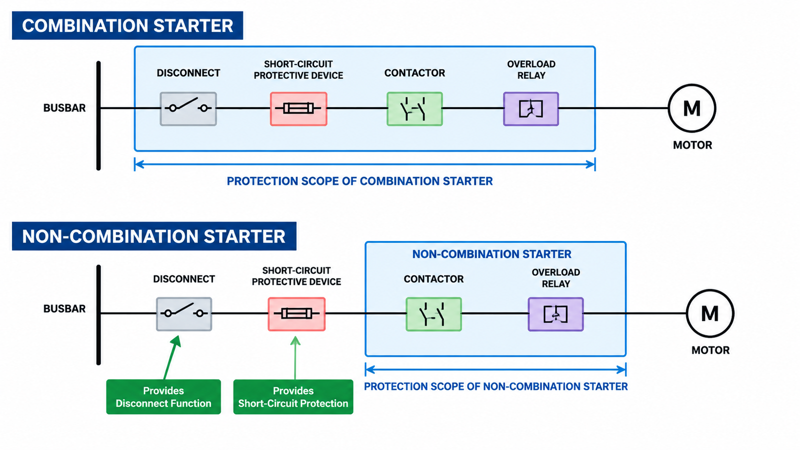
A combination starter vs non-combination starter decision comes down to one question: does the assembly include the branch-circuit disconnecting means and short-circuit protection, or does it rely on a device installed somewhere else? A combination starter packages the disconnect, the short-circuit protective device, the contactor and the overload relay into one listed assembly. A non-combination starter provides only the contactor and overload, so the branch protection and isolation have to come from upstream equipment. That single difference drives enclosure size, wiring scope, fault rating, coordination strategy and maintenance practice — which is why it is worth settling before you price a panel. This guide covers what each assembly contains, how the two behave under fault conditions, and how to choose between them for a motor branch circuit in an AC contactor based control system.
If you only remember one table from this article, make it this one. The motor control function is identical in both designs. What changes is how much of the branch circuit travels with the starter.
| Function | Combination starter | Non-combination starter |
|---|---|---|
| Start / stop the motor | Yes — contactor inside | Yes — contactor inside |
| Overload protection | Yes — overload relay inside | Yes — overload relay inside |
| Branch-circuit short-circuit protection | Yes — fuse, MCCB or listed self-protected controller | No — provided upstream |
| Disconnecting means | Yes — disconnect or breaker handle on the enclosure | No — separate disconnect or lockable upstream device |
| Typical home | Motor control centre bucket, packaged skid, local motor station | Custom multi-motor panel, OEM machine, centralised protection scheme |
| Field wiring responsibility | One feeder in, one motor out | Feeder, protection and isolation split across the panel |
The practical consequence is that a non-combination starter is not a complete motor branch circuit. It is one link in a chain that somebody else has to close.
Strip away the marketing and a motor starter has always been three things: a switching device that carries and breaks motor current, an overload element that responds to sustained excess current, and a control interface that decides when to switch. In the simplest direct-on-line arrangement, that is a contactor, a thermal overload relay and a start-stop circuit.
If you are still separating the roles of the switching device and the starter assembly, the guide to selecting a contactor for a motor starter covers the sizing logic in detail. The point here is narrower: neither the contactor nor the overload relay is allowed to clear a short circuit. That job belongs to a separate protective device, and whether that device sits inside the same enclosure is exactly what separates the two starter types.
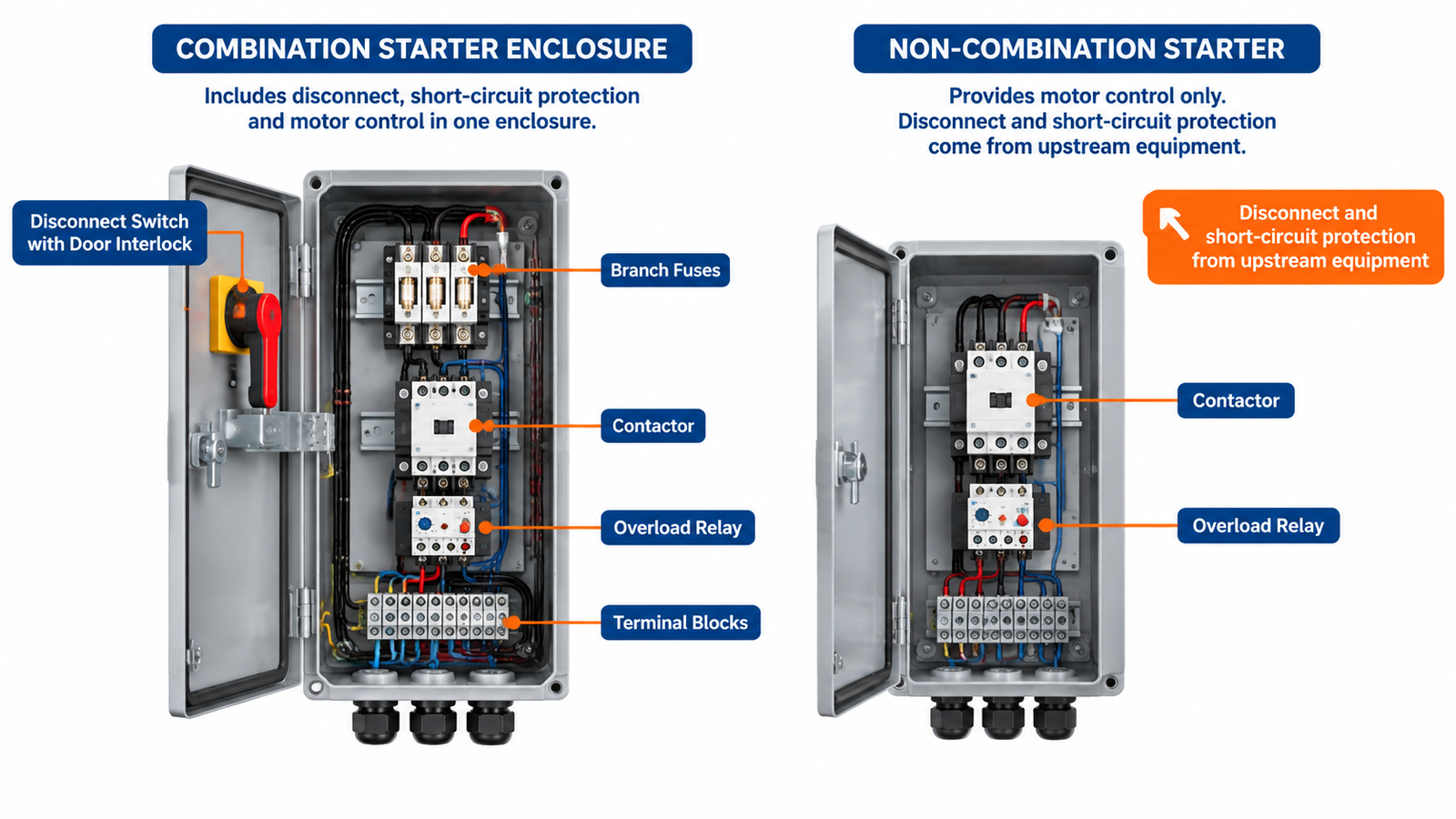
A combination starter is a motor starter assembly that also contains the disconnecting means and the branch-circuit short-circuit protective device for that motor. Everything needed to isolate, protect and control one motor is inside one enclosure, tested and listed as a unit.
Many combination starters also include a control-circuit transformer, a start-stop pushbutton station and auxiliary contacts for interlocking. Once those are inside, the assembly becomes a self-contained local control station rather than a component bundle.
In North American practice, UL 508 recognises several arrangements of listed combination motor controller, and the letter designations matter when you are comparing quotations. The arrangement most engineers mean by “Type E” is a combination starter built around a self-protected combination motor controller — a manual motor controller with integral magnetic short-circuit trip that is tested with the contactor and overload as a listed combination. It collapses the disconnect and the branch protection into one compact device and removes the fuse block from the enclosure.
A Type F arrangement carries the overload function inside the branch protective device itself. Both designs are legitimate, but neither is a drop-in substitute for a fuse-plus-disconnect combination: the short-circuit rating, the magnetic trip setting and the permissible motor size all change, and the rating only holds for the exact combination that was tested. Always read the listing mark and the combination table on the device rather than assuming that a higher interrupting rating on the breaker alone makes the assembly suitable.
A non-combination starter contains the contactor, the overload relay and the control interface — and stops there. It has no integral disconnect and no integral short-circuit protection. The motor branch is completed by equipment installed elsewhere: a feeder breaker in the same panel, a group-mounted fuse block, a busbar-mounted MCCB, or the main protective device of a machine.
This is not a cheaper or lower-grade product. It is a deliberate architecture. In a custom panel feeding twelve small motors, twelve individual disconnects and twelve sets of branch fuses may be worse engineering than one properly rated feeder group with a single lockable isolation point per section. The non-combination starter exists because centralised protection is sometimes the better design.
Beyond the component list, five differences decide most projects.
| Criterion | Combination starter | Non-combination starter |
|---|---|---|
| Branch-circuit protection | Integral and tested with the assembly | External; coordination must be engineered |
| Isolation for maintenance | Local, at the enclosure door | Remote or shared; needs a lockable device |
| Fault rating (SCCR) | Published for the complete assembly | Must be calculated for the panel as built |
| Panel footprint | Larger per motor | Smaller per motor, larger shared equipment |
| Installation labour | One feeder in, one motor out | More internal wiring and terminal work |
| Fault diagnosis | One enclosure to open | Two locations to check |
| Best fit | MCC buckets, packaged equipment, retrofit | Multi-motor panels, OEM machines, centralised schemes |
Most electrical codes require a disconnecting means for the motor circuit that can be locked in the open position, and many require it to be within sight of the motor or capable of being locked where it is not. A combination starter satisfies this by construction because the disconnect is part of the starter. A non-combination starter pushes the requirement upstream, so either the feeder device must be lockable and acceptably located, or a separate local isolator has to be added — which erodes much of the cost advantage.
The short-circuit current rating of an assembly is set by its weakest link, not by its best component. A panel full of contactors with a 50 kA interrupting device upstream does not automatically have a 50 kA rating; it has whatever the listed combination supports, which may be far lower. Combination starters come with an assembly rating you can quote directly. Non-combination arrangements require the panel builder to establish the rating through testing or through a listed series combination, and to document it.
This is the most common place where a project that looked cheaper at the component level becomes expensive at the approval stage. If the available fault current at the MCC is 25 kA and the proposed starter components are only listed for 10 kA in combination, the design fails regardless of the upstream breaker’s rating.
IEC 60947-4-1 defines two coordination levels. Under Type 1 coordination, the contactor and overload relay may be damaged after a short circuit and are expected to be replaced; the requirement is that no danger results. Under Type 2 coordination, no damage is permitted other than light welding of contacts that can be separated, and the device must remain serviceable.
Type 2 coordination is only demonstrated by a tested combination of a specific contactor, a specific overload and a specific short-circuit protective device. That is much easier to guarantee inside a single listed combination starter than across a panel where the protective device and the starter come from different suppliers. If your specification calls for Type 2, the combination starter is usually the shorter path to compliance. For the boundary between switching duty and protective duty, see contactor vs circuit breaker.
A combination starter needs more enclosure volume per motor but less engineering per motor. A non-combination design inverts that: smaller per-motor footprint, more shared equipment, more internal wiring and more documentation. In a panel with three large motors, the difference is marginal. In a panel with forty small motors, it is decisive in both directions — forty combination buckets consume serious wall space, while forty non-combination starters require a protection scheme that is genuinely coordinated.
For maintenance staff, the combination starter is unambiguous: open one door, isolate one device, verify dead, work. The non-combination arrangement requires knowing which upstream device feeds which starter, which is exactly the kind of knowledge that disappears when the original panel schedule is lost. If your site relies on contractors and shutdown windows are short, the local isolation point is worth real money.
Take a 90 kW, 400 V, three-phase centrifugal pump with a nameplate full-load current of 160 A. A 170 A AC-3 frame such as the CJX2-D170 contactor covers that duty with normal margin, and the overload is set at 160–168 A, subject to the motor manufacturer’s service factor guidance.
Now add the branch circuit. A direct-on-line start draws roughly six to eight times full-load current for a few seconds, so the magnetic trip or fuse must ride through 960–1280 A without operating while still clearing a genuine fault. In a combination starter, that device sits in the same enclosure and its rating is published with the assembly. In a non-combination design, the same calculation has to be done against whatever feeder device the panel designer selected — and the short-circuit rating of the resulting combination has to be verified, not assumed.
If the motor is sized correctly in the first place, the contactor choice barely changes between the two designs. The contactor sizing chart applies either way. What changes is everything around it.
| Situation | Better fit | Why |
|---|---|---|
| Motor control centre with individual buckets | Combination | Per-bucket isolation and protection is the standard MCC pattern |
| Packaged skid or OEM machine shipped as a unit | Combination | One feeder connection simplifies commissioning and certification |
| Retrofit into an existing plant room | Combination | Avoids running new upstream circuits and re-documenting the panel |
| Custom panel with many small motors on shared feeders | Non-combination | Centralised protection is more economical and easier to coordinate |
| Panel where the upstream device is already listed and lockable | Non-combination | Duplicating isolation adds cost without adding safety |
| Specification requires Type 2 coordination | Combination | Tested combinations are easier to prove inside one assembly |
| Very tight enclosure space, low fault level | Non-combination | Smaller per-motor footprint if the protection scheme is sound |
| Mistake | What goes wrong |
|---|---|
| Treating the overload relay as short-circuit protection | The overload responds to thermal build-up, not to fault current. It will not clear a short circuit safely. |
| Quoting a non-combination starter without confirming the upstream device | Isolation and branch protection become someone else’s scope, usually discovered at commissioning. |
| Assuming the assembly SCCR equals the breaker rating | The rating belongs to the listed combination. A high-rated breaker in front of an untested combination does not raise it. |
| Mixing brands inside a Type 2 combination | Coordination is demonstrated per combination. Substituting a contactor voids the evidence. |
| Adding a disconnect to a non-combination starter without re-rating | The added device changes the short-circuit path and may invalidate the original rating. |
The choice is not about which starter is better built. It is about how much of the motor branch circuit you want to own inside one enclosure. Combination starters buy certainty: a tested assembly, a published fault rating, local isolation and simpler field wiring. Non-combination starters buy flexibility and panel density, at the cost of engineering work that has to be done properly elsewhere. Decide which of those you are actually purchasing before the quotation is fixed, because changing your mind later usually means changing the panel.
If you are specifying starters for a project, the AC contactor range covers frames from small control duty up to 170 A AC-3, with matching thermal overload relays.
Yes. A combination starter contains the contactor and the overload relay in addition to the disconnecting means and the branch-circuit short-circuit protective device. All four functions are inside the same listed assembly.
No. The motor branch circuit still needs a disconnecting means that can be locked open, and it still needs branch-circuit short-circuit protection. Those functions simply come from equipment installed upstream rather than from the starter enclosure.
The hardware usually costs more, but the installed cost often does not. Fewer field terminations, one feeder per motor, no separate disconnect to mount and a published fault rating can offset the component premium, especially on retrofits where upstream work is disruptive.
Short-circuit current rating is the maximum fault current the assembly can withstand without posing a hazard. For a combination starter it is published for the tested assembly. For a non-combination arrangement it must be established for the panel as built, and it is limited by the weakest component in the combination.
You can add a local isolator, but the assembly then has to be re-evaluated as a combination. Adding a device into the fault path can change the short-circuit rating and the coordination evidence, so the new arrangement needs to be verified rather than assumed.
IEC practice does not use the combination and non-combination vocabulary in the same way, but the functional split is identical. A starter with an integral manual motor starter or motor protection circuit breaker behaves like a combination starter; a contactor and overload fed from a group-protected busbar behaves like a non-combination starter.