3 Hacks to Test a Contactor: No-Tool Diagnostic Skills
Published: Author: Lisa
Your contactor stops pulling in, the motor will not start, and the panel is a forty-minute drive away — and your multimeter is in the van you did not bring. Here is the good news: you can still test a contactor with nothing but your eyes, your ears, and one fingertip. Most contactor faults announce themselves physically before they show up on a meter, and a structured no-tool inspection will tell you which of the three failure stages you are dealing with — the control circuit, the coil, or the main power contacts — before you open a single enclosure cover twice.
This guide walks through three field-proven diagnostic hacks, explains exactly what each physical sign means mechanically, and ends with a 60-second triage order you can run on any AC contactor in service. When the inspection does point to a meter, you will know precisely which measurement to take first.
Why Diagnose Without Instruments First
A contactor is an electromechanical device, and electromechanical devices fail in visible, audible, and tangible ways. The coil burns and darkens its own winding. Contacts pit, weld, and soot their arc chutes. Armatures stick, springs weaken, and loose terminals leave heat halos on the plastic beside them. None of that requires a meter to observe — it requires knowing where to look and what the sign means.
No-tool triage also has a practical payoff: it prevents the most expensive mistake in contactor diagnosis, which is replacing a healthy unit because the real fault lives in the control circuit. A contactor that never receives coil voltage is not a failed contactor. Sight, sound, and touch separate those cases in under a minute.
Hack 1 — Read What You Can See
With the panel isolated and locked out, start with a slow visual pass. You are looking for the physical evidence each failure mode leaves behind.
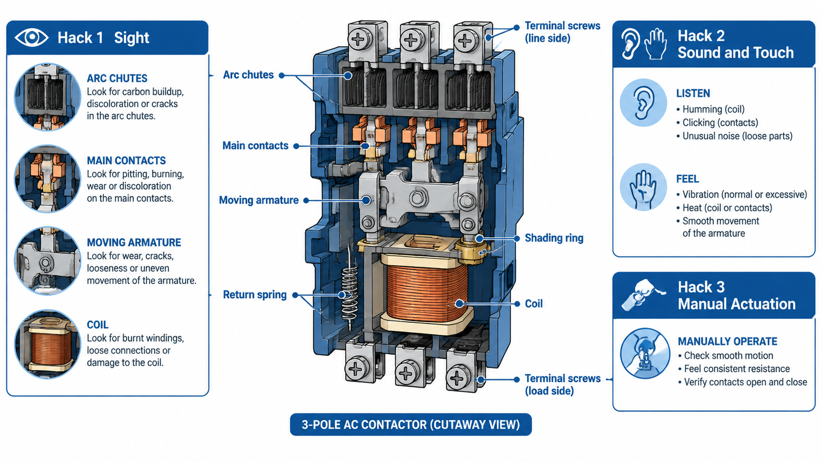
The inspection map: every no-tool diagnostic points at one of these seven physical locations.
The terminal heat halo
Look closely at the plastic housing around each line and load terminal. A loose or corroded connection raises contact resistance, and resistance at high current means heat. That heat bleeds into the surrounding plastic and leaves a yellow-brown halo, sometimes with a bloomed or crazed surface texture. A halo on one phase where the other two are clean is one of the most reliable no-instrument findings in panel work — the contactor body may be fine, but that terminal is a fault in progress.
Contact faces and arc chutes
On contactors with visible contact pads or removable covers, read the contact surface like a wear gauge. New contacts are silver-grey and smooth. Light grey frosting is normal aging. Dark soot, deep pitting, or a cratered edge means the contacts have been arcing beyond their design duty — usually from frequent switching of a load they were never sized for. If two contacts have fused into a welded bridge, the load will stay live even with the coil de-energized, which is a stop-everything safety finding, not a maintenance item.
The arc chutes tell the same story from a different angle. These ceramic or polymer splitters sit directly above the contacts and catch the arc every time the contactor breaks load. A chute caked with carbonized soot means heavy breaking duty; a cracked or missing chute fragment means the next arc will have nowhere to go.
Coil and body clues
The coil itself usually hides behind the contact assembly, but its failure signatures surface on the outside. Darkened or bulging molded coil housing, varnish discoloration around the coil window, or a smell of burnt enamel all point to a coil that has overheated — commonly from sustained undervoltage or from a control contact that never fully opened. Moisture ingress shows as white-green corrosion at the coil terminals.
Loose or corroded connection — re-torque, do not condemn the contactor yet
Pitted, sooted or cratered contact pads
Contact wear past design duty — replacement likely
Soot-caked or cracked arc chute
Heavy breaking duty or wrong rating for the load
Darkened, bulged or varnish-stained coil housing
Coil overheating — check control voltage and control contact
White-green corrosion at coil terminals
Moisture ingress — dry, seal, and re-test
Melted or discolored moulding near main contacts
Sustained overload — verify the contactor rating against the load
Hack 2 — Listen to the Pull-In Signature
Restore control power only, and command the contactor to close. A healthy contactor answers with a single, crisp, mechanical thunk — one sound, no aftermath. Everything else on the audio spectrum is evidence:
Silence. No movement, no click. The coil is either not being energized at all (control circuit) or it is open (failed coil). Put a hand on the housing: a totally cold body with no sound usually means the coil never saw voltage — a control problem, not a contactor problem.
Loud hum or buzz. A steady 100/120 Hz hum on an AC coil means the armature is not seating fully, so the magnetic circuit has an air gap and the shading ring cannot smooth the flux. Causes include debris in the pole faces, a broken shading ring, or a misaligned armature. The coil draws locked-rotor current continuously in this state and will cook itself if left energized.
Chatter. Rapid pull-in/pull-out cycling points at the control side: voltage sagging below the coil’s hold-in threshold, a loose control wire, or an interposing relay bouncing. The mechanical system is healthy; the supply to it is not.
Double-click or sluggish pull-in. A soft, two-stage clunk suggests mechanical friction or a weakened return spring fighting the armature travel.
De-energize first, then rest a fingertip on the coil housing — not on any conductor — for a count of three. You are reading temperature as a fault signature:
Warm but touchable. Normal. Coils run warm by design.
Too hot to keep your finger on after only a count of three. The coil is overheating — consistent with the buzz-and-not-seat condition above, chronic undervoltage, or a shorted turn count.
Stone cold while the system supposedly runs. The coil never energized. The contactor is being blamed for a control-circuit fault.
Hot at the terminals, cold at the coil body. The heat is from a bad connection at the terminal, not the coil — go back to Hack 1’s halo inspection.
Use the back of your finger if you are unsure about how hot something is; it pulls away faster and is more sensitive than the palm side.
Hack 3 — Force the Mechanism and Feel the Answer
Most industrial contactors from roughly 9 A upward can be actuated by hand — either a marked manual test button on the top cover or, with power fully isolated, a firm even press on the visible armature through the contact area using an insulated tool. This is the only hack that directly exercises the mechanism, and it answers a question no other check can: is the switching function mechanically sound?
What the press tells you
Smooth travel with a firm end-stop, and it stays closed while pressed. The mechanism and main contacts are mechanically sound. If the contactor still will not work electrically, the fault is in the coil or its supply — a coil diagnosis, not a contactor replacement.
Gritty, uneven travel or a spongy end-stop. Debris, contact material fragments, or armature wear inside the mechanism. Plan replacement.
It does not stay closed under finger pressure even with the mechanism undamaged. The return spring or armature alignment has failed.
The known-good substitution
Where spares exist, substitution remains the fastest field verdict of all. Swapping the coil from a known-good contactor of the same voltage class is a two-minute test: if the fault follows the coil, the coil is dead; if the fault stays with the frame, the mechanism or contacts are the problem. Swapping the complete contactor isolates the device from everything around it. Just keep the substitution disciplined — same pole count, same AC-3/AC-1 duty rating, same coil voltage — otherwise you are introducing a second variable. The A1/A2 coil terminal and control wiring conventions make the swap straightforward even on unfamiliar panels.
The 60-Second Triage Order
Run the hacks in this sequence. Each one narrows the fault space before the next begins:
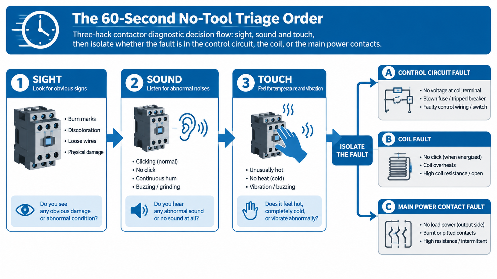
The no-tool triage order: three checks, three verdicts.
Sight (20 seconds). Terminal halos, contact faces, arc chutes, coil housing. Already found a halo or a welded contact? Stop — you have your answer.
Sound and touch (20 seconds). Command closure, listen to the signature, then fingertip the coil housing. Silence with a cold body points at the control circuit; hum or chatter points at seating or supply; a clean thunk with no output points at the main contacts.
Manual actuation (20 seconds). With power isolated, press the mechanism. Smooth travel clears the mechanical system and closes the case.
One caution before you accept a “bad contactor” verdict: check that the trip was not an overload relay doing its job. If the contactor is simply staying open because the overload relay in the starter circuit has tripped, the contactor itself is innocent — reset the relay and find why it tripped instead.
What No-Tool Diagnostics Cannot Tell You
The three hacks localize the fault to a stage; they do not quantify it. They cannot measure coil resistance against the datasheet, distinguish a 10 % undervoltage from a 25 % one, or detect a single shorted turn in a winding that otherwise behaves. They also cannot verify contact resistance against the milliohm-level limit that separates “aged” from “worn out”.
That is exactly what the meter is for — and why the triage order matters. Arriving at the multimeter with a verdict of “control circuit, no coil voltage” turns a dozen possible measurements into one: check for voltage at the coil terminals. If the no-tool inspection leaves you needing numbers, follow the multimeter step-by-step test for coil, main and auxiliary contacts — it picks up precisely where these hacks end.
Safety Lines You Do Not Cross
Lock out before touching. Every visual and manual check in this guide happens with the panel isolated, locked, and proved dead where practical. Sound tests are the only exception, and they involve no contact.
Never inspect contacts under load. Opening a contactor cover while its contacts carry current exposes you to the arc, not just the voltage.
Respect stored energy. The return spring holds mechanical energy even when everything is de-energized. Keep fingers out of the contact gap during a manual press.
Treat the temperature test as a touch, not a grip. If the surface is hotter than expected, your reflex will handle it — if you are gripping, it will not.
Arc-rated PPE above 50 V. If the diagnosis requires energized work on a higher-voltage control circuit, that is a meter-and-PPE job, not a no-tool one.
When the Diagnosis Says Replace
Some findings end the discussion. Welded contacts, cracked arc chutes, a coil with visible thermal damage, and contact pads worn to their backing are replacement items — contactors are not rebuilt in the field, and a unit that has arced past its design duty will fail again on schedule, not on warning. When replacing, match pole count, utilization category (AC-3 for motor duty, AC-1 for resistive), the AC-3 rated current against the load, and the coil voltage to the control circuit — not to what is in the spares bin.
For standard three-phase motor and resistive loads, the CJX2 series three-phase AC contactor covers the common 9–95 A AC-3 range with AC and DC coil voltage options, which makes it a practical like-for-like replacement in most industrial panels.
결론
You do not always need instruments to test a contactor — you need a method. Sight reads the physical evidence each failure mode leaves behind. Sound decodes the pull-in signature into a verdict on the coil and its supply. Manual actuation proves the mechanism itself. Run them in that order and, in about a minute, you will know whether the fault lives in the control circuit, the coil, or the contacts — and whether the meter is even necessary. When it is, you will arrive at the right measurement the first time, and when the verdict is replacement, you will know exactly which rating plate fields to match.
자주 묻는 질문
Can I really test a contactor without a multimeter?
You can reliably determine which stage has failed — control circuit, coil, or contacts — using sight, sound, and manual actuation. You cannot measure coil resistance, verify contact milliohms, or quantify undervoltage without a meter. Use the no-tool hacks for triage, then confirm with instruments when numbers are needed.
What does a healthy contactor sound like when it closes?
A single, crisp, positive thunk with no follow-on noise. A continuous hum means the armature is not seating, chatter means the coil voltage is unstable, and total silence means the coil is not being energized or has failed open.
My contactor body is cold and silent. Is the contactor dead?
Not necessarily — that combination usually means the coil never received voltage at all. Before condemning the contactor, check the control circuit upstream: control fuses, interlocks, the switching relay or thermostat output, and the control wiring itself.
Is it safe to press the armature manually?
Yes, with the main power isolated and locked out, and using an insulated tool or the manufacturer’s manual test button rather than a bare finger near the contact gap. Never do it under load — that is how arc exposure and unexpected motor start events happen.
Can I clean pitted contacts instead of replacing the contactor?
Light surface oxidation can be dressed, but pitting and soot mean material has been eroded away; filing restores geometry, not the silver-alloy contact surface or its thickness. Once contacts are pitted, replacement is the reliable option — and it costs less than a return visit.
How do I tell a bad contactor from a tripped overload relay?
If the contactor’s coil is being commanded but the unit stays open, check the overload relay in the starter first. A tripped overload holds the control circuit open, so the contactor behaves exactly like a failed one. Reset and investigate the trip cause before touching the contactor.
Modular contactors are the structural switching layer of modern control panels. Covers the control chain, the 17.5 mm module grid, IEC 61095 vs IEC 60947-4-1, coil integration and thermal design.
Seven specifications decide whether a modular contactor survives or fails: utilization category, current and derating, poles, coil supply, duty, rail space and protection.
Modular and traditional AC contactors are built for different duty. Compare standard, utilization category, coil design, panel space and cost, then use the decision matrix to specify the right one.