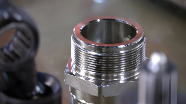
Brass Cable Gland Nickel-Plated IP68 Waterproof Industrial Grade
BCG-200 brass cable gland for factories, suppliers, exporters, and distributors. Supports bulk purchase, custom OEM/ODM, wholesale pricing, and private label.
Read More
Cable gland sizing confuses a lot of buyers because the gland is named after its thread (M20, PG16, 1/2″ NPT) but is actually selected by the outer diameter of the cable it clamps. A “cable gland size chart” only works once you accept this rule: conductor cross-section (1.5 mm², 185 mm²…) tells you the approximate cable OD, and the cable OD tells you the gland. This guide gives you the full mapping from 1.5 mm² to 400 mm² conductors across Metric, PG and NPT thread systems, plus panel hole sizes and the mistakes that cause leaks and failed IP68 tests.
Every cable gland has three dimensions that matter, and only one of them is printed in the product name:
The gland does not care how many conductors are inside the cable or their cross-section; it only grips the jacket. Conductor area matters indirectly — more copper means a bigger cable and a bigger jacket. That is why the tables below map conductor size to typical OD, and you must confirm with your actual cable’s OD before ordering.
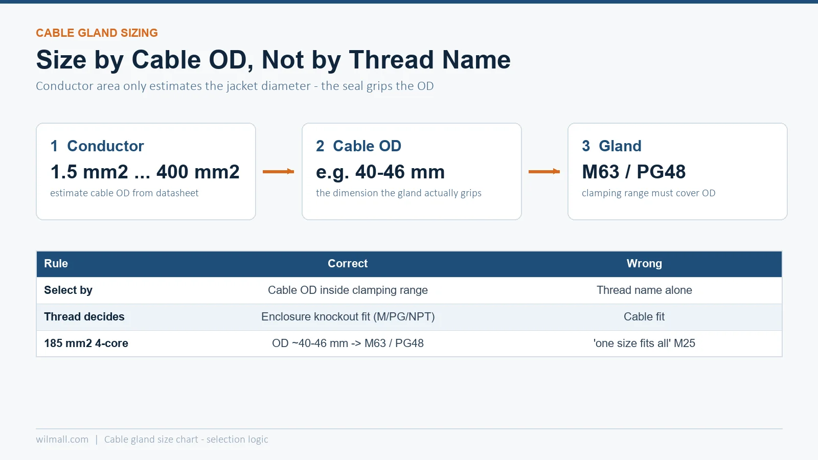
Metric glands follow ISO metric threads with a 1.5 mm pitch (M20×1.5, M25×1.5…). They are the default in IEC markets — Europe, the Middle East, Asia and Australia. The chart below maps common conductor cross-sections (multi-strand copper, unarmoured control or power cable) to typical overall OD and the gland that clamps it:
| Conductor (mm²) | Typical cable OD (mm) | Metric gland | Clamping range (mm) |
|---|---|---|---|
| 1.5 | 6–9 | M16 | 4.5–10 |
| 2.5 | 7–11 | M16 / M20 | 4.5–13 |
| 4 | 9–13 | M20 | 6–13 |
| 6 | 10-14 | M20 / M25 | 6–18 |
| 10 | 12–16 | M25 | 12–18 |
| 16 | 14–19 | M25 | 12–18 |
| 25 | 17–23 | M32 | 18–25 |
| 35 | 19–25 | M32 | 18–25 |
| 50 | 22–28 | M32 / M40 | 18–32 |
| 70 | 24–32 | M40 | 25–32 |
| 95 | 28–36 | M40 / M50 | 25–38 |
| 120 | 30–38 | M50 | 32–38 |
| 150 | 33–41 | M50 / M63 | 32–50 |
| 185 | 37–46 | M63 | 42–50 |
| 240 | 42–52 | M63 / M75 | 42–55 |
| 300 | 46–56 | M75 | 48–60 |
| 400 | 50–62 | M75 / M80 | 52–65 |
Values are indicative for unarmoured 4-core control and power cables. A 3-core, single-core or armoured cable of the same conductor size can be several millimetres different in OD — always check the cable datasheet and match it to the gland’s clamping range, not to this table alone.
For large single cables entering an enclosure — 185 mm² and above — a wide-range large-diameter metal cable gland such as the M32A stainless series family is the usual choice, because the long clamping seal holds heavy cable weight without crushing the insulation.
PG (“Panzer-Gewinde”) threads are an older German standard still extremely common on control cabinets, junction boxes and sensors shipped to markets where German equipment is installed. PG gland sizes are fixed by DIN 40430, and the thread outside diameter also tells you the panel hole:
| PG size | Thread OD (mm) | Typical clamping range (mm) | Panel hole (mm) |
|---|---|---|---|
| PG7 | 12.5 | 3-6.5 | 12.5 |
| PG9 | 15.2 | 4-8 | 15.2–16 |
| PG11 | 18.6 | 5-10 | 18.6–19 |
| PG13.5 | 20.4 | 6-12 | 20.4–21 |
| PG16 | 22.5 | 8–14 | 22.5–23 |
| PG21 | 28.3 | 13–18 | 28.3–29 |
| PG29 | 37.0 | 18–25 | 37 |
| PG36 | 47.0 | 25–32 | 47 |
| PG42 | 54.0 | 30–38 | 54 |
| PG48 | 59.3 | 34–44 | 59.3–60 |
Need the single most common PG size in depth — thread dimensions, hole size, drill diameter and wrench torque for PG9 specifically? See the PG9 cable gland specification guide, which covers the gland that fits the 4–8 mm cables used by most sensors and small control boxes.
NPT glands (ANSI/ASME B1.20.1 taper thread) dominate North American panels and any export project where the enclosure follows UL practice. NPT is a tapered thread, so sealing relies on thread engagement plus sealant or an O-ring, and the gland body is sized in inches:
| NPT size | Typical clamping range (mm) | Rough metric equivalent |
|---|---|---|
| 1/2″ | 6-12 | M20 |
| 3/4″ | 11–18 | M25 |
| 1″ | 17–25 | M32 |
| 1-1/4″ | 24–32 | M40 |
| 1-1/2″ | 30–38 | M50 |
| 2″ | 37–45 | M63 |
A useful cross-reference habit for mixed projects: size the gland by cable OD first, then convert to whichever thread system the enclosure uses. The clamping insert stays the same; only the thread body changes.
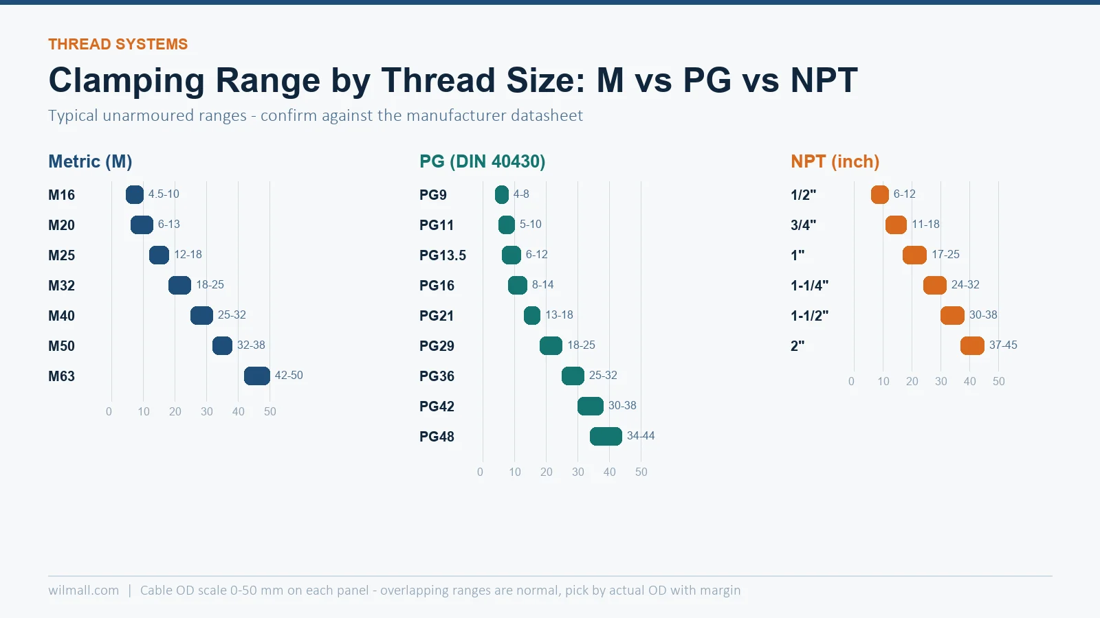
Buyers often ask “what gland fits a 4-core 10 mm² cable?” — the query behind many size searches. The safe procedure is:
For example, a 4-core 185 mm² cable usually has an OD near 40–46 mm, which is why “185 sq mm cable gland size” searches land on M63 or PG48 glands. A 400 mm² single-core lands closer to 55–62 mm, needing M75/M80. If the OD falls between two glands, choose the larger one and verify the seal can still compress — a gland gripped below its minimum range will leak, and one forced above its maximum will crack the seal insert.
When you drill the enclosure instead of using pre-made knockouts, use the hole the locknut needs — not the thread’s minor diameter:
| Gland thread | Typical panel hole (mm) | Locknut across flats (mm) |
|---|---|---|
| M16 | 22 | 24 |
| M20 | 27.5 | 30 |
| M25 | 33 | 36 |
| M32 | 42 | 46 |
| M40 | 53 | 55 |
| M50 | 63 | 65 |
| M63 | 74 | 80 |
Deburr the hole, keep the sealing gasket flat against the wall, and torque the locknut against the gland body — an over-torqued plastic gland deforms the thread; an under-torqued metal gland lets the gland rotate and loosen the cable seal. For material and IP trade-offs between nylon, brass and stainless bodies, the cable gland types overview breaks down when each body material is worth the cost.
Typically M63 metric or PG48, because the cable OD of a 4-core 185 mm² cable sits around 40–46 mm. Confirm with the actual cable OD and the gland’s clamping range before ordering.
Always cable OD. The gland’s sealing insert grips the jacket, so the clamping range must cover the actual OD. Conductor size is only a proxy for estimating OD.
Both clamp similar cables (roughly 6–13 mm OD), but the threads are incompatible: M20 is a 1.5 mm pitch metric thread, PG16 is a DIN 40430 thread with 22.5 mm OD. Match the thread to the enclosure knockout, not the cable.
About 33 mm — the hole must accept the gland body plus locknut. Always deburr and keep the flat sealing gasket in place to maintain the IP rating.
Yes, if their ODs fall inside one clamping range. Many projects standardise on M20 and M32 bodies with different seal inserts rather than ordering a new thread size per cable.