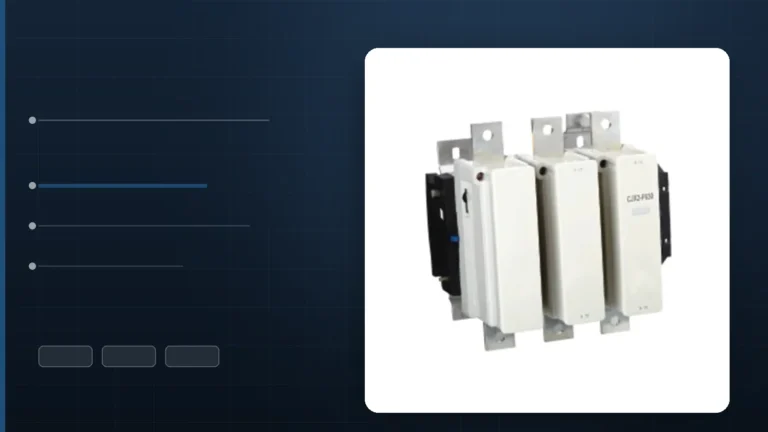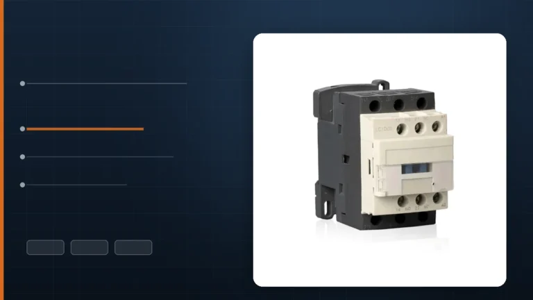
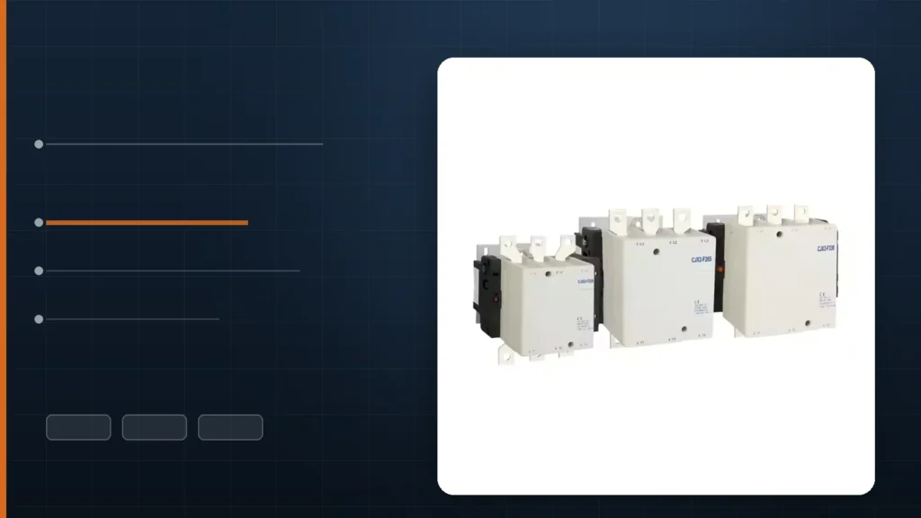
For a resistive heater, do not size the contactor from the AC-3 motor column. A heater element draws essentially its full current from the first cycle — nichrome cold resistance is only about 5 to 10 % below its hot value — so there is no inrush to absorb, but there is also no thermal margin to borrow. The number that governs is the contactor’s AC-1 / thermal current rating (Ith) at the ambient inside your enclosure. On the same frame that figure is typically 1.2 to 2.2 times the AC-3 rating: our CJX2-D115 is rated 115 A at AC-3 380 V and 200 A at AC-1, θ ≤ 40 °C.
Heater panels are the quiet corner of contactor selection. Nobody argues about them, because a resistance bank looks like the easiest load in the plant — no starting current, no power factor correction, no torque curve. That is exactly why they get sized by copying the motor table next door, and why we regularly see 30 % to 50 % of the contactor’s usable capacity thrown away on ovens, duct heaters, mould heaters and furnace banks.
This article works through the three numbers that actually decide a heater contactor — the AC-1 rating, the enclosure ambient and the cycling rate — using the ratings published on our own CJX2-F series 그리고 LC1-D series data sheets, and shows where a contactor stops being the right device at all.
Why the AC-3 Column Is the Wrong Number
Utilisation categories are not a quality scale; they are a description of the test the contactor passed. Under IEC 60947-4-1, AC-3 asks the device to make 6 to 10 times its rated current and break 1 times it, because the test models a squirrel-cage motor: the contacts close into a locked rotor, then open a running motor. The frame is therefore built around two things a heater never does — closing into an inrush, and interrupting a running inductive current.
AC-1 asks for something much milder: make 1.5 times the rated current at a power factor of 0.95, and break 1.5 times at the same power factor. A resistance furnace meets that description by definition. Almost nothing in the contactor’s mechanical or thermal design is being stressed, which is why the same physical device carries far more current under AC-1 than under AC-3.
| 매개변수 | AC-3 (motor duty) | AC-1 (resistive / furnace) |
|---|---|---|
| Making current, multiple of Ie | 6 × (10 × up to 17 A) | 1.5 × |
| Breaking current, multiple of Ie | 1 × | 1.5 × |
| Test power factor | 0.35 – 0.65 | 0.95 |
| What limits the rating | Arc energy at make, contact erosion | Terminal and contact temperature rise |
| Typical use on this page | Fans, pumps, compressors, conveyors | Ovens, duct heaters, furnaces, mould heaters |
One practical warning: you will find simplified tables that give AC-1 as “1× making and breaking”. That shorthand survives because on a resistive load the binding constraint is thermal, not the arc — the contactor reaches its temperature-rise limit long before its breaking capacity. Use 1.5× as the standard figure and Ith as the real ceiling.
The Rating You Actually Need: AC-1 and Thermal Current
Most contactor data sheets do not print an “AC-1” column at all. They print Ith, the conventional thermal current — the current the device carries continuously in an enclosure at a stated ambient, without exceeding the permissible temperature rise, with no switching duty implied. For a resistive load, Ith and AC-1 are the same conversation, and the big-frame sheets say so explicitly: the CJX2-D115 / D150 data sheet labels its 200 A and 250 A figures “rated heating current AC-1, θ ≤ 40 °C”.
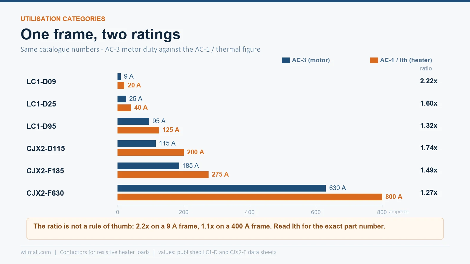
Here is what that looks like across the frames we supply. The last column is the resistive load a three-phase 400 V heater bank can be, at unity power factor, on the AC-1 figure — it is the number a heater customer actually wants to read.
| 모델 | AC-3 at 380 V | AC-1 / Ith at 40 °C | Ratio | Heater load at 400 V, 3-phase |
|---|---|---|---|---|
| LC1-D09 | 9 A | 20 A | 2.22 × | 13.9 kW |
| LC1-D18 | 18 A | 32 A | 1.78 × | 22.2 kW |
| LC1-D25 | 25 A | 40 A | 1.60 × | 27.7 kW |
| LC1-D40 | 40 A | 60 A | 1.50 × | 41.6 kW |
| LC1-D95 | 95 A | 125 A | 1.32 × | 86.6 kW |
| CJX2-D115 | 115 A | 200 A | 1.74 × | 138.6 kW |
| CJX2-F185 | 185 A | 275 A | 1.49 × | 190.5 kW |
| CJX2-F400 | 400 A | 440 A | 1.10 × | 304.8 kW |
| CJX2-F630 | 630 A | 800 A | 1.27 × | 554.2 kW |
Two things fall out of that table. First, the ratio is not constant — it narrows as the frame grows, from 2.2× on a 9 A device to 1.1× on a 400 A one, because on large frames the AC-3 rating is already close to the thermal limit. Second, the ratio is not a rule of thumb you can carry between brands. Always read the actual Ith for the exact catalogue number.
A 75 kW Heater Bank, Sized Twice
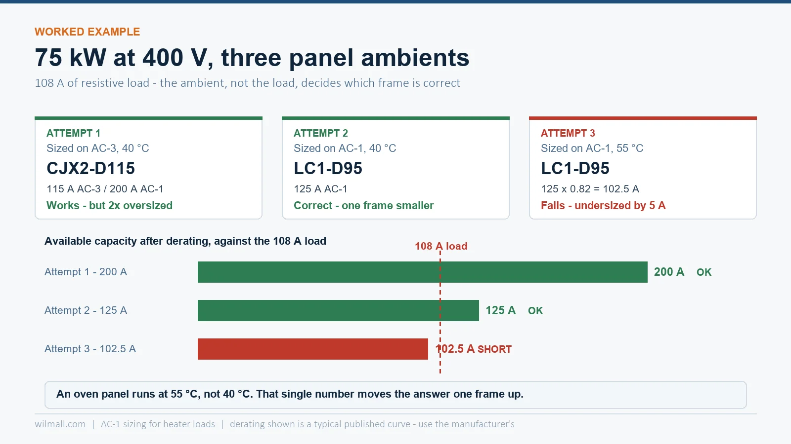
Take a 75 kW, three-phase 400 V resistance bank — a powder-coat oven, a drying tunnel, a large mould heater. At unity power factor:
I = 75,000 ÷ (1.732 × 400) = 108 A
Attempt 1 — sized on AC-3, 40 °C panel. 108 A of AC-3 needs a 115 A frame. On AC-1 that frame carries 200 A. You have bought roughly twice the device you need, and you will pay for it in coil VA, panel space and copper.
Attempt 2 — sized on AC-1, 40 °C panel. LC1-D95 carries 125 A under AC-1, comfortably above 108 A. One frame smaller, one third less panel area, and the contacts are doing exactly the duty they were tested for.
Attempt 3 — the same AC-1 sizing, 55 °C panel. This is where it breaks. An oven panel is not a 40 °C panel; the contactor sits beside the element terminals. Apply the published derating for 55 °C, roughly 0.82: 125 × 0.82 = 102.5 A, which is below the 108 A load. The LC1-D95 is now undersized, and the next frame up — CJX2-F115 at 200 A AC-1 — derated to 164 A, is correct.
That third attempt is the whole article in one example. AC-1 sizing is only as good as the ambient you apply to it.
Ambient Derating: The Number Everyone Forgets
Every Ith figure on a contactor data sheet is qualified by an ambient — 40 °C on the frames above, sometimes 55 °C on larger industrial ranges. Above that reference the device must be derated, because the same watts of contact and terminal loss now sit in hotter air. Published curves differ between manufacturers, but the shape is consistent:
| Enclosure ambient | Typical Ith multiplier | What it looks like in practice |
|---|---|---|
| 40 °C | 1.00 | Reference point on the data sheet |
| 45 °C | 0.95 | Ordinary machine-room panel |
| 50 °C | 0.90 | Panel next to a heated process line |
| 55 °C | 0.82 | Oven or furnace panel — the common real case |
| 60 °C | 0.75 | Above this, reconsider the panel, not the contactor |
Three practical notes. The ambient to use is the air temperature inside the enclosure, not the room temperature — a sealed panel beside an oven routinely runs 10 to 15 °C above the workshop. Elements wired in delta dissipate more heat inside the cabinet than the same kW in star. And a heater bank has a second thermal load the motor case never has: the element terminals themselves, which radiate into the same compartment. If your panel has no fan and no louvre, assume 55 °C and size accordingly.
What a Heater Load Really Does to Contacts
Resistive does not mean harmless. Four behaviours separate a heater circuit from a motor circuit, and each one has a design consequence.
- Almost no inrush, but a small one. Nichrome and Kanthal elements have a small temperature coefficient; cold resistance runs roughly 5 to 10 % below hot resistance, so the first-cycle current is only about 1.05 to 1.10 times steady state. Nothing to design for — and nothing that a bigger frame will fix.
- Element failure is a fault, not an overload. A heating element at end of life usually fails open, which is safe, but it can also fail as a short between turns or to earth. The contactor is not a protective device; the branch fuse or breaker and, on metal-sheathed elements in wet areas, an earth-leakage device, carry that duty. Do not delete branch protection because “it is only a heater”.
- Duty cycle, not load, consumes the contacts. A PID time-proportioning controller on a 30-second cycle gives 120 operations per hour, 24 hours a day — roughly 1 million operations a year. That is the same contact-wear budget a heavily jogged motor uses, and it is the reason a heater contactor often fails electrically long before it fails thermally. Our datasheet guide shows how to turn the published operations figure into a service life.
- Thermal cycling cooks the terminals. Repeated heat-up and cool-down loosens screwed terminations. Heater panels are the single most common source of high-resistance joints we see in the field. Retorque at commissioning and at the first service interval.
Cycling Frequency Decides the Technology
Once the operations per hour climb, the contactor stops being the cheapest answer even though it is the cheapest device. This is the one selection question where a heater customer genuinely needs a different product, not a bigger contactor.
| Electromechanical contactor | Solid-state relay | Thyristor power unit | |
|---|---|---|---|
| Practical switching rate | Up to roughly 30 operations per hour | Hundreds per minute, zero-cross or random | Continuous phase-angle or cycle control |
| Arc and contact wear | Yes — the limiting life factor | None | None |
| Off-state leakage | None — true isolation | Milliamps; the load stays partly live | Milliamps |
| Heat in the panel | Coil only, a few watts | About 1.2 W per ampere per pole, on a heatsink | Higher; needs forced cooling at rating |
| Failure mode | Fails open, or welds closed | Fails shorted — the heater runs uncontrolled | Fails shorted or open, per device |
| Cost index (contactor = 100) | 100 | 60 – 150 | 400 – 900 |
The failure mode line matters more than the price line. An SSR that fails shorted leaves a 75 kW bank energised with the controller reading “off” — a genuine fire risk on a drying oven. That is why serious heater panels keep a contactor as the upstream disconnect in front of an SSR or thyristor unit, and why that contactor can be sized on AC-1 with confidence: it switches only a handful of times per shift.
Wiring Rules That Apply Only to Heater Circuits
Three rules come up in every heater panel review we do.
Switch all poles. On a three-wire motor circuit, breaking two phases interrupts the current, because there is no return path. On a heater bank with a star point or a neutral, a two-pole device can leave an element at line potential with the controller showing “off”. Use a three-pole contactor for a three-phase heater, four-pole for a three-phase-plus-neutral group, and treat the contactor as a control device — not as the maintenance isolator.
Do not parallel poles to double the current. It is the most persistent myth in heater panels. Two poles of one contactor never share current equally: their closing instants scatter by one to three milliseconds, so the first pole to touch carries the whole load through its own arc, and the first to open breaks nearly all of it. Paralleling gives you far less than double, and it concentrates all the wear on one pole. Connecting poles in series is the legitimate technique — but that splits arc voltage for higher-voltage or DC duty, it does not raise current capacity.
Size the cable for the element tolerance, not the nameplate. Resistance wire is sold to a tolerance of several percent, and a cold element measures low. A 75 kW bank can draw 5 % over nameplate on a cold start and still be within specification. Design at 90 % of the AC-1 rating and leave the rest as margin.
Five Sizing Mistakes We See on Heater RFQs
- Sizing on the AC-3 kW column. It answers a motor question. The heater number is Ith at your ambient.
- Quoting at 40 °C for an oven panel. The single largest cause of premature heater-contactor failure, and the easiest to fix.
- Adding an overload relay. A thermal overload protects a motor against sustained overload. On a fixed resistance it protects nothing useful and adds a heat source inside the panel — branch protection is the correct device.
- Ignoring the operations count. A 30-second PID cycle uses up a contactor in two to three years at 24/7. Ask for the cycle time before you quote.
- Specifying an SSR without a contactor. Cheap until the SSR fails shorted and the oven cannot be switched off.
자주 묻는 질문
What utilisation category is a resistance heater?
AC-1 — non-inductive or slightly inductive loads, including resistance furnaces, with a power factor of 0.95 or better. IEC 60947-4-1 tests AC-1 at 1.5 times rated current for both making and breaking.
Can I use a standard AC-3 contactor on a heater?
Yes, and it is completely safe — but size it on the AC-1 / Ith figure, not the AC-3 figure. Using the AC-3 number is not wrong electrically, it just makes you buy one or two frames larger than the duty requires.
Why is the AC-1 rating so much higher than the AC-3 rating?
Because AC-3 requires the contacts to close into 6 to 10 times rated current and interrupt an inductive running current, so the frame is designed around arc energy and contact erosion. AC-1 requires 1.5 times and a near-unity power factor, so the limit becomes simple temperature rise — which the same copper and silver handle at a much higher current.
Do heating elements have an inrush current?
Barely. Nichrome and similar resistance alloys have a small temperature coefficient, so cold resistance is only about 5 to 10 % below the hot value and the first-cycle current is 1.05 to 1.10 times steady state. Incandescent and quartz-tungsten lamps are the exception — tungsten cold resistance is a fraction of its hot value, giving 10 to 15 times inrush. Those are AC-5b loads, not AC-1, and must not be sized as heaters.
Can I parallel two poles of a contactor for a bigger heater?
No. Contacts do not share current equally because they do not close at the same instant, so the wear and the arc concentrate on whichever pole operates first. Use the next frame size. Series connection of poles is valid for arc-voltage splitting, not for extra current.
Contactor or solid-state relay for a heater bank?
Under about 30 operations per hour, a contactor sized on AC-1 is cheaper, cooler in the panel and gives true isolation. Above that — short PID cycles, fast-response furnaces, high-accuracy zones — an SSR or thyristor unit wins on life, and should still have a contactor upstream as a disconnect.
Which contactor do you recommend for a 75 kW oven at 400 V?
108 A of load at 55 °C panel ambient needs an AC-1 rating of at least 120 A after derating. That is the CJX2-F115 frame — 200 A AC-1 at 40 °C, 164 A at 55 °C. The full frame range is listed in our AC contactor catalogue.
If you are sizing a heater circuit and want the AC-1 figure confirmed against a specific element tolerance and enclosure ambient, send us the kW, voltage, phase and panel temperature — we will return the frame, the coil voltage and the branch protection in one sheet.