Types of Modular Contactors: A Practical Selection Guide
Types of modular contactors explained: poles, AC-7a vs AC-7b duty, NO vs NC contact forms, latching types and coil options, with an application-to-type selection matrix.
Read More
In a thermal overload relay vs MPCB comparison, both devices protect a motor against sustained overload, and that is where the similarity ends. A thermal overload relay is a control-circuit device: it detects thermal overload and tells a contactor to drop out. An MPCB (motor protection circuit breaker) is a main-circuit device: it combines thermal overload, magnetic short-circuit and — on most models — phase-failure protection, and it breaks the load current itself. Which one you need depends on how the motor is switched, how much fault current is available, and how much panel space you have. This guide compares the two on protection scope, switching endurance, trip classes, coordination and cost, and shows a worked direct-on-line selection using an AC contactor based circuit.
| 측면 | Thermal overload relay | MPCB |
|---|---|---|
| Overload protection | Yes — bimetallic or electronic | Yes — thermal element integrated |
| Short-circuit protection | No — needs a fuse or breaker upstream | Yes — instantaneous magnetic trip |
| Phase failure / imbalance | Differential models only | Standard on most three-phase models |
| Isolation function | No — opens the coil circuit only | Yes — suitable for isolation use |
| Can it switch the motor on and off? | No — a contactor does the switching | Only occasionally — low switching endurance |
| Position in the circuit | After the contactor, under it | Before the contactor, feeding it |
| Typical Icu (breaking capacity) | Not rated — relies on the SCPD | 25–100 kA depending on frame |
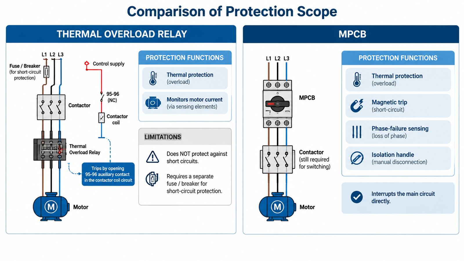
A thermal overload relay never touches the load current path when it operates. Motor current flows through its heating elements or current transformers, and when the thermal image of the motor says “too hot for too long”, the relay opens a normally closed auxiliary contact — the 95–96 contact — wired in series with the contactor coil. The contactor de-energises, and its main contacts interrupt the motor current. The working principle, contact functions and differential phase-loss mechanism are covered in detail in the thermal overload relay guide.
This architecture has a hidden advantage that most comparisons miss: the contactor is doing the current breaking, and a contactor is built for it. An AC-3 rated contactor is engineered for tens of thousands of load-switching operations and around a million mechanical operations. The relay itself, as a sensing element, barely wears at all. If you need frequent start-stop cycling — a compressor, a mixer, a conveyor with many starts per hour — that endurance is exactly what you want handling the current.
The corresponding limitation: the relay has no breaking capacity of its own. A fault current ten to fifty times full-load current will destroy it, so a short-circuit protective device must sit upstream. That device also has to be coordinated with the relay and contactor so that the relay survives currents it can handle and hands off everything above that to the fuse or breaker.
An MPCB puts the thermal overload element, the magnetic instantaneous trip and a manual operator mechanism in one housing, and connects them to the main circuit. When it trips, it interrupts the motor current directly, through contacts rated for fault interruption at its declared Icu — commonly 50 kA or more at 400 V on mid-range frames. Most models also trip differentially on phase loss, which protects three-phase motors from the single-phasing condition that basic overload relays miss.
What it does not replace is the contactor. Two reasons:
So in practice most motor circuits end up as MPCB + contactor + (often) nothing else, or breaker + contactor + thermal relay. The real question is not “relay or MPCB” but “where do I want the short-circuit and isolation functions to live”.
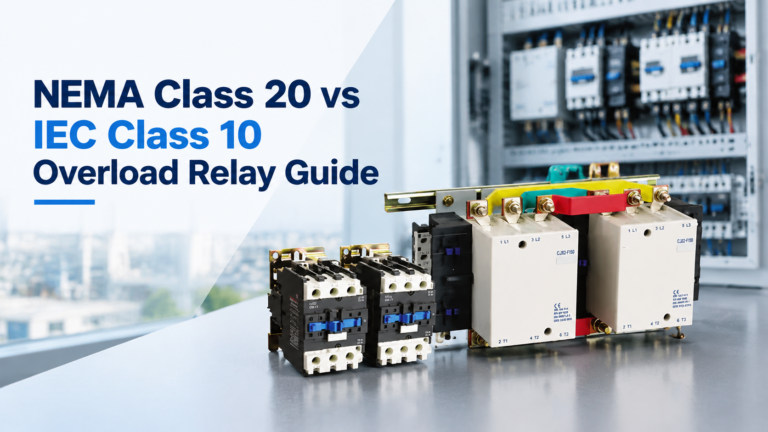
Trip class defines how long the relay tolerates starting current before tripping — Class 10 trips within 10 seconds at 7.2 times setting, Class 20 within 20 seconds, Class 30 within 30. Most MPCBs are fixed at Class 10, with a few models offering Class 20. Dedicated thermal overload relays are available across Class 10, 20 and 30, and electronic models go further with selectable curves.
High-inertia loads — fans, centrifuges, flywheels, loaded crushers — can draw near locked-rotor current for 15 to 40 seconds while accelerating. Put a Class 10 MPCB in front of one and it will nuisance-trip during every start. That is a specification problem, not a defective device. The overload relay selection guide walks through matching trip class to starting time. When the load is high-inertia, the usual answer is a Class 20 or 30 thermal relay plus a separate short-circuit device — which is precisely the combination an MPCB was meant to replace, until the application said otherwise.
Under IEC 60947-4-1, a motor starter is judged by its coordination with the short-circuit device. Type 1 coordination accepts damage to the contactor after a short circuit, as long as nothing dangerous escapes. Type 2 requires the contactor to stay serviceable apart from light contact welding. Type 2 is demonstrated per tested combination: one contactor model, one relay or MPCB model, one SCPD or MPCB rating. Mixing brands inside a claimed Type 2 combination voids the evidence, whoever you bought it from.
An MPCB makes Type 2 documentation simple because the tested combination is usually the same manufacturer’s MPCB plus contactor table. A thermal relay plus fuse line is equally valid — fuses provide current limiting that often makes Type 2 easier at high fault levels — but the combination table you cite must actually cover the fuse class, size and relay model you installed.
In the North American market the calculation changes: UL 508A requires the complete combination to be listed, and MPCB-based combinations have historically been the slower path, with fuse-plus-overload arrangements more familiar to panel shops and inspectors. Export-oriented projects should decide this per destination, not by habit.
| 요인 | Thermal relay + SCPD + contactor | MPCB + contactor |
|---|---|---|
| Component count | 3 devices plus terminal work | 2 devices |
| Panel width (typical small frame) | Wider — relay under contactor plus separate breaker | Compact — 45 mm MPCB plus contactor |
| Upfront hardware cost | Lower per component | Higher per component, fewer of them |
| Wiring labour | More terminations | Fewer terminations |
| Short-circuit breaking capacity | Whatever the fuse or breaker provides (100 kA common for fuses) | 25–100 kA depending on model |
| Trip class choice | 10 / 20 / 30 freely selectable | Usually Class 10 only |
| Local isolation | Only if the SCPD is a switch-disconnector | Yes, integral handle |
| Reset after trip | Via relay reset, contactor re-closes | Via MPCB handle |
| Typical failure to catch | Phase loss (on non-differential models) | High-inertia starts (Class 10) |
Nuisance tripping deserves its own paragraph in both architectures: it is almost always a mismatch between device characteristic and load behaviour rather than a faulty device. The MCB tripping guide covers the diagnostic sequence, and the same logic applies to both MPCBs and overload relays. For the reset procedure itself — including when you should not reset at all — see how to reset an AC contactor.
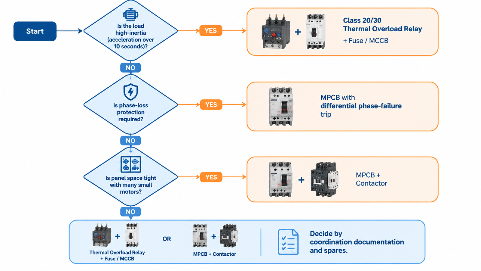
Contrast two motors to see the logic in action.
Motor A — 7.5 kW centrifugal fan, 15 A full load, accelerating for 25 seconds. High inertia. An MPCB set to 15 A with Class 10 will trip during the start. Spec: contactor for switching duty (an LC1-E frame at 18 A AC-3 has margin), a Class 20 or 30 thermal relay set to 15 A, and a gG or aM fuse or MCCB upstream for short-circuit duty. This is the classic three-device circuit, and it exists for a reason.
Motor B — 4 kW conveyor, 9 A full load, starts in 2 seconds, PLC-controlled with 30 starts per hour. Low inertia, high cycling. A 9–10 A MPCB feeding the contactor gives short-circuit, phase-loss and isolation in one compact device, and the contactor absorbs the switching duty it is built for. The MPCB wins on space, wiring time and phase-loss coverage.
Same plant, same voltage, opposite answers — decided by starting time and switching frequency, not by brand or price.
| 조건 | Better choice |
|---|---|
| High-inertia load, long acceleration | Thermal relay (Class 20/30) + separate SCPD |
| Frequent start-stop cycling | Either, with the contactor doing the switching — check phase-loss needs |
| Phase-loss risk on a three-phase motor | MPCB, or a differential thermal relay |
| Very tight panel, many small motors | MPCB + contactor |
| High available fault current (above MPCB Icu) | Thermal relay + current-limiting fuses |
| Type 2 coordination with minimal documentation | MPCB + matching contactor from one tested combination table |
| UL/NA panel build | Whichever combination is already listed for your components |
| Spare-parts simplicity across mixed motor sizes | Thermal relays — wide setting ranges, one contactor series |
| Mistake | Consequence |
|---|---|
| Using the MPCB handle as the routine start-stop switch | Operator mechanism wears out long before its protection capability does; end-of-life switching failures follow. |
| Installing an MPCB on a high-inertia fan without checking trip class | Repeated nuisance trips during start; someone eventually bypasses protection entirely. |
| Assuming the overload relay provides short-circuit protection | The relay is destroyed on the first fault; upstream device must clear it. |
| Claiming Type 2 with mismatched brands | No valid coordination evidence exists; insurance and acceptance issues surface later. |
| Sizing the relay to the motor service factor without checking the nameplate | Setting above or below full-load current either misses overloads or trips on normal duty. |
A thermal overload relay and an MPCB are not two grades of the same product. The relay is a precise thermal sensor that borrows the contactor’s switching capability; the MPCB is a self-contained protector that still needs a contactor for control. Choose by starting time, switching frequency, phase-loss risk and fault level — and when a specification simply says “motor protection”, ask which of those four variables is actually driving it. For switching duty in either architecture, the AC contactor range covers the frames these devices protect.
No. A thermal overload relay only opens an auxiliary contact in the control circuit; something must break the load current. That is the contactor’s job, which is why the relay and contactor are always paired in motor circuits.
In almost every practical motor circuit, yes. The MPCB provides protection and occasional manual switching, but remote start-stop control, interlocks and cycling duty all require a contactor’s coil and its high switching endurance.
A thermal overload relay with Class 20 or Class 30 trip characteristics plus a separate short-circuit device. Most MPCBs are fixed at Class 10 and will nuisance-trip during long acceleration periods.
Most three-phase MPCBs include differential phase-failure tripping as standard. Basic thermal overload relays without differential sensing will not detect a single-phasing condition promptly, since the remaining phases may not exceed the set current.
Per component, no; per circuit, usually yes. The MPCB replaces the separate breaker, fuse block and terminal work, and the reduced wiring labour typically offsets its higher unit price on small and mid-size motors.
The device in the fault path — the MPCB or the fuse — must have an interrupting rating at or above the available fault current at its installation point. Fuses commonly offer 100 kA or more; MPCBs range from about 25 kA to 100 kA by frame, so verify against your supply data rather than assuming.