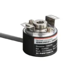
The GOH38AO1 incremental rotary encoder combines compact design, high precision, and robust performance tailored for industrial automation systems. Featuring a 38mm diameter and semi-hollow 8mm shaft, this encoder delivers reliable position and speed feedback with pulse resolutions up to 10,000 PPR. It supports diverse output signal options including line driver and open collector, making it compatible with various PLCs and control platforms. Built for durability, it withstands demanding environments while ensuring smooth operation for motors, conveyors, robotics, packaging, and CNC machinery.
Key Features
Incremental rotary encoder with resolutions from 100 to 10,000 pulses per revolution for ultra-fine motion detection
Semi-hollow shaft design (8mm diameter) facilitates direct motor mounting and easier installation
Robust 38mm diameter compact housing suitable for various industrial applications
Wide operating voltage range: 5-24 V DC to fit different control systems
Multiple output types including line driver (differential), open collector, and push-pull outputs
Integrated anti-interference circuit for stable, noise-resistant signal output
High-speed response suitable for fast-moving machinery and high-frequency applications
Reliable mechanical construction ensures long operational life and low maintenance
Product Advantages
High resolution enables precise speed and position control in advanced automation setups
Semi-hollow shaft enables easy shaft coupling and reduces installation complexity
Versatile output options enhance compatibility with a broad range of industrial equipment and PLCs
Compact design saves space without compromising performance or durability
Noise protection circuits guarantee signal integrity in electrically noisy environments
Wide voltage tolerance supports flexible system design and retrofit scenarios
Product Model And Meaning
| G | 0 | H | 38 | 01 | 1000 T | 3 | 0.7M | ||||||
| Category of product | Type of product | Form of main shaft | Contour of product | Size of main shaft,shaft hole | Outlet and sealing form | Outline structure | Resolution | Output form | 输出信号 Outputsignal | 电缆线 Cable | |||
| G:incremental type | megneto- electricity | H:semi- hollow shaft | 38:φ38mm | 口:φ8mm | A:rubber wire protection sleeve | 01:outline structure1 | 10,20,50, 60,100, 200360, 400,500, 600,800, 1000,1024, 1200,2000, 2048,2500, 3000,3600, 4096等 | C:open collector output F:complementary output L:5V drive output | 1:phaseAsignal 2:phase AB signal 3:phase ABZsignal 4:phase ABA/B/ signal 5: phase ABZA/B/Z/ signal | Default 0.7m line,For non 0.7m, labeling is sufficient | |||
Wiring Table
| Line color | C/F output signal | – | Line color | Loutput signal |
| red | VCC | red | VCC | |
| black | GND | |||
| black | GND | |||
| green | A phase | |||
| green | A phase | white | B phase | |
| yellow | Z phase | |||
| white | B phase | |||
| blue | Aphase | |||
| yellow | Z phase | gray | Bphase | |
| orange | Z phase | |||
| shield | F ·G | |||
| shield | F ·G |
Output Phase Difference
complementary output/NPN collector open circuitoutput/push pull output


long line drive output


Mechanical Drawings(mm)


Application Scenarios
High-precision industrial motor speed and position control
Robotics requiring fine motion control and feedback
Conveyor systems in packaging and manufacturing lines
CNC machines for accurate cutting and positioning
Printing machinery for synchronized roller and sheet control
Automated assembly lines requiring reliable rotary feedback
Installation & Maintenance
Ensure the application shaft matches the 8mm semi-hollow shaft for seamless coupling.
Carefully align the encoder to prevent shaft misalignment and reduce wear. Flexible couplings are recommended.
Secure the encoder housing firmly using mounting screws to avoid vibration.
Connect power supply within 5 to 24 V DC, adhering to polarity and wiring diagrams for your output type.
Use shielded cables for signal wires to minimize electromagnetic interference.
Periodically clean the encoder surface to prevent dust accumulation.
Routinely inspect wiring and connectors for tightness and signal stability.
Replace encoder if signal loss or mechanical damage is detected.
Request a Quote Now
Our team will get back to you within 24 hours.


