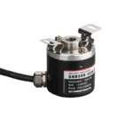
The GOH38B incremental rotary encoder is designed for accurate motion control and reliable position feedback in diverse industrial applications. Featuring an optical sensing system with multiple resolution options and a robust compact 38mm housing, this encoder withstands tough environments while delivering consistent performance. Its wide voltage range, various output signals, and IP65-rated protection make it an ideal choice for machinery, automation systems, robotics, and packaging equipment requiring precision and durability.
Key Features
High-resolution incremental encoder with pulse counts ranging from 100 to 2500 PPR
Rugged IP65 protection against dust and moisture for extended service life
Standard 38mm diameter and 6mm shaft for versatile mounting compatibility
Wide operating voltage range from 5 to 24V DC
Multiple output signal options including open-collector (NPN), push-pull, and line driver types
Durable aluminum shell enhances mechanical strength and vibration resistance
Supports A, B, and Z phase signals including differential outputs for precise direction and position tracking
Operating temperature range suitable for most industrial environments
Product Advantages
Delivers accurate and repeatable position and speed feedback essential for precise motion control
Robust IP65 rating protects internal components in harsh industrial settings
Compact and lightweight design ensures easy integration in space-limited machinery
Flexible output configurations support a wide variety of control systems and automation interfaces
High mechanical and electrical stability reduces downtime and maintenance needs
Compatible with high-speed and high-resolution applications, improving system efficiency
Product Model And Meaning
| G | 0 | H | 38 | □ | E | 600 | F | 3 | 2M | |||
| Category of product | Type of product | Form of main shaft | Contour of product | Size of main shaft,shaft hole | Outlet and sealing form | Resolution | Output form | Output signal | Cable | |||
| G:incremental type | O:megneto- electricity L:photoelec- tricity | H:semi- hollow shaft | 38:φ38mm | □:φ6mm | E:side outlet metal | 10,20,50, 60,100, 200,360, 400,500, 600,800 1000,1024,1 200,2000,20 48,2500,300 0,3600,5000 | C:open collector output F:complementary output T:push pull output L:5V drive output A:24V drive output | 1:phase Asignal 2:phase AB signal 3:phase ABZ signal 4: phase ABA/B/ signal 5:phase ABZA/B/Z/ signal | Default 2m line,For non 2m, labeling is sufficient |
Wiring Table
| Line color | C/F output signal | – | Line color | Loutput signal |
| red | VCC | red | VCC | |
| black | GND | |||
| black | GND | |||
| green | A phase | |||
| green | A phase | white | B phase | |
| yellow | Z phase | |||
| white | B phase | |||
| brown | Aphase | |||
| yellow | Z phase | gray | Bphase | |
| orange | Z phase | |||
| shield | F ·G | |||
| shield | F ·G |
Output Phase Difference
complementary output/NPN collector open circuitoutput/push pull output


long line drive output


Mechanical Drawings(mm)


Application Scenarios
Industrial automation equipment requiring precise rotational measurement
CNC machinery for accurate tool positioning and speed control
Printing and packaging machines for synchronized operation and counting
Robotics requiring reliable feedback for joint and wheel positioning
Conveyor belt speed and position monitoring in manufacturing lines
Elevators and escalators for shaft position sensing and speed feedback
Installation & Maintenance
Clean the mounting area and verify compatibility with the 6mm shaft diameter.
Align the encoder shaft carefully with the driven equipment shaft; flexible couplings are recommended to minimize stress.
Secure the encoder firmly using the mounting holes to prevent vibration during operation.
Connect the power supply (5-24V DC) and ensure correct wiring for your selected output type.
Shield signal cables to prevent electromagnetic interference and ensure stable signal transmission.
Perform periodic inspection for dust accumulation and clean the encoder surface gently without harsh chemicals.
Check connector and cable integrity regularly to maintain signal quality.
Replace encoder if signs of mechanical wear or signal inconsistencies appear.
Request a Quote Now
Our team will get back to you within 24 hours.


