


Heavy-Duty 38mm Shaft Incremental Rotary Encoder Model GOS38A04
The GOS38A04 Incremental Rotary Encoder is designed for precise motion and position feedback in demanding industrial automation environments, with rugged construction and stable output signals, ensuring long-lasting performance in diverse automation and motion control systems.
Interested in this product?
Please contact our sales team for the latest pricing, lead time, and technical consultation.
The GOS38A04 Incremental Rotary Encoder is designed for precise motion and position feedback in demanding industrial automation environments. Featuring a robust 38 mm shaft and customizable resolution up to 600 pulses per revolution (PPR), this encoder delivers reliable and accurate AB quadrature signals ideal for speed, position, and direction sensing applications. Engineered for durability, the encoder supports versatile installation with rugged construction and stable output signals, ensuring long-lasting performance in diverse automation and motion control systems.
Key Features
Solid 38 mm shaft diameter for heavy-duty usage
Customizable resolution up to 600 PPR for precise measurement
Standard AB quadrature output signals with high noise immunity
Robust construction suitable for industrial environments
Supports both clockwise and counterclockwise rotation detection
Optional zero pulse (Z channel) for reference marking and homing
Product Advantages
High accuracy and repeatability increase system reliability
Durable mechanical design with resistance to vibration and shock
Flexible output options allow easy integration with PLCs, controllers, and industrial drives
Long operational lifespan with stable performance in harsh conditions
Low starting torque reduces wear and extends gearbox and motor life
Cost-effective solution with maintenance-friendly design
Product Model And Meaning
| G | 0 | S | 38 | □ | A | 04 | 1000 T | 3 | 2M | ||||
| Category of product | Type of product | Form of main shaft | Contour of product | Size of main shaft,shaft hole | Outlet and sealing form | Outline structure | Resolution | Output form | Output signal | Cable | |||
| G:incremental type | 0:megneto- electricity | S:solid shaft | 38:φ38mm | □:φ6mm | A:side outlet rubber | 04:4 outline structure4 | 10,20,50, 60,100, 200,360, 400,500 600,800, 1000,1024,1200, 2000,2048,2500,3000,3600, 4096 | T:push pull output L:5V drive output A:24V drive output | 1Aphase Asignal 2:ABphase AB signal 3:ABZphase ABZ signal 4:phase ABA/B/ signal 5:phase ABZA/B/Z/ signal | Default 2m line,For non 2m, labeling is sufficient | |||
Wiring Table
| Line color | T output signal | – | Line color | L/A output signal |
| brown | VCC | brown | VCC | |
| blue | GND | |||
| blue | GND | |||
| black | A phase | |||
| black | A phase | white | B phase | |
| orange | Z phase | |||
| white | B phase | |||
| black red | Aphase | |||
| orange | Z phase | white red | Bphase | |
| orange red | Z phase | |||
| shield | F ·G | |||
| shield | F ·G |
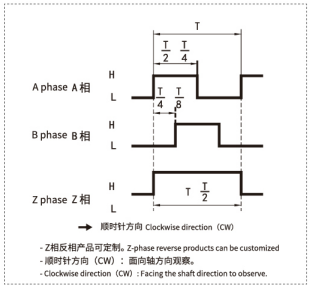
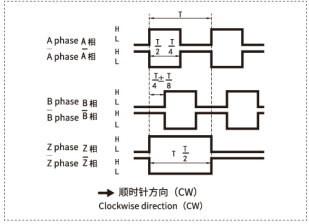
Output Phase Difference
push pull output
longline drive output
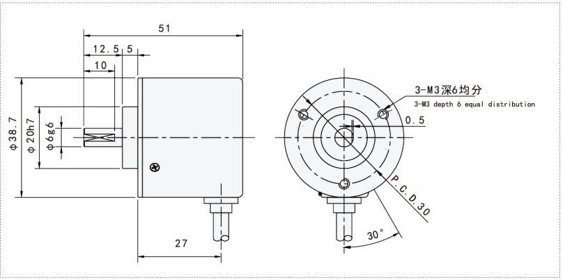
Mechanical Drawings(mm)
Installation Steps & Maintenance
Secure the encoder shaft firmly to the rotating equipment shaft, ensuring proper alignment to avoid mechanical stress.
Connect the encoder output cables to your control system inputs, verifying wiring according to ABZ signal specifications.
Set the desired resolution and pulse count if customization is available; otherwise, use default factory settings.
Perform initial rotation tests to confirm signal output and direction detection accuracy.
Periodically inspect the encoder and connections for dirt, debris, or wear and clean gently to maintain optimal function.
Lubricate bearings if specified in the user manual (most models are sealed and maintenance-free).
Applications
Industrial automation and robotics requiring precise angular position feedback
CNC machinery for tool positioning and speed control
Conveyor systems and packaging machines for accurate motion monitoring
Printing machinery for synchronized speed and position sensing
Medical device instrumentation requiring high-precision rotary feedback
Elevators and escalators for motor position verification