BRHB-T1 SPD Backup Protector
Every surge protective device needs something in front of it to clear a short circuit. On paper a miniature circuit breaker or a fuse will do the job, and on most days it does. The problem appears on the day the surge protector fails: the current that follows is not a clean fault current, and a device selected only by its ampere rating can react in ways that either take the board offline during a storm or fail to clear the fault at all. The BRHB-T1 is a dedicated SPD backup protector built to sit in series ahead of the surge device and get that distinction right.
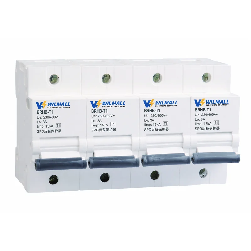
It is a four-pole unit for 230/400 V systems with a 3 A rated current and an impulse withstand of 15 kA, marked as a T1 companion for a Type 1 surge protector.
Why an Ordinary Breaker Gets This Wrong
A surge protector spends almost all of its life doing nothing, then conducts a current that has nothing in common with a normal load. Two failure modes follow from that.
- A breaker with a thermal element tuned for a modest rating can treat the impulse as an overload and open on a legitimate surge, leaving the installation unprotected at the exact moment protection was needed.
- A breaker selected for a high rating can ride through the impulse but then fail to open quickly when the surge device fails into a short circuit, leaving a sustained fault on the board.
Both outcomes come from the same root cause: an ordinary breaker is designed around a load, and a surge path is not a load. An SPD backup protector starts from the opposite assumption, treating the branch as a fault path that has to stay closed during an impulse. Its current profile is a spike followed by a follow current, and the protective device has to be able to tell those two apart.
What the BRHB Does Differently
Selective trip segmentation
The mechanism inside the BRHB uses a changed current parameter to separate the two regimes. The element responds to the sustained current of a failed surge device but does not accumulate enough energy from the short impulse to operate. In practice that means the device rides through the event it is supposed to ride through, and only operates when there is a genuine fault to clear.
Low residual voltage across the backup itself
Anything in series with the surge path adds voltage while the surge is flowing. A backup device with a high residual impedance lifts the clamping voltage that the protected equipment sees, which quietly cancels part of the protection that was paid for. The BRHB is built with a low residual impulse voltage for that reason, and its performance in this respect is better than an open-type switch or a fuse holder.
Fast clearing with a defined number of operations
The range is characterised at a prospective short-circuit current of 50 kA with a clearing time around 0.3 s, and a power-frequency breaking capacity of a thousand operations. Those figures describe a device that is meant to be reused after clearing a fault rather than replaced like a fuse.
Two Versions for Two Stages
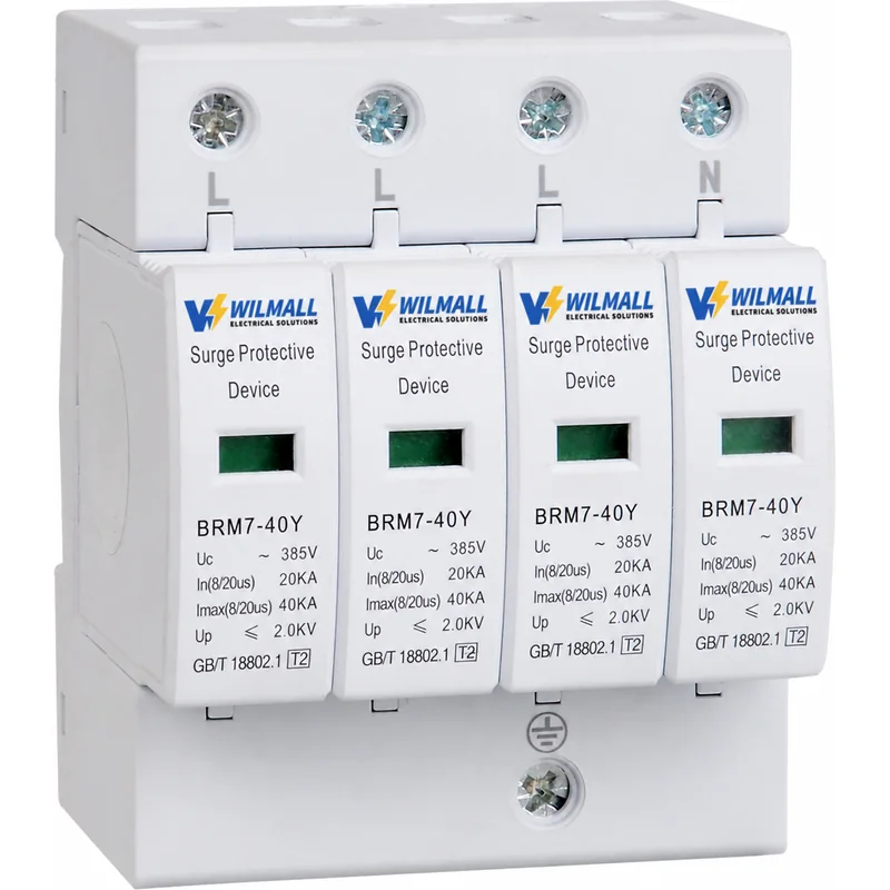
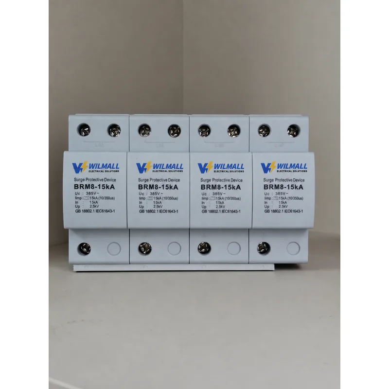
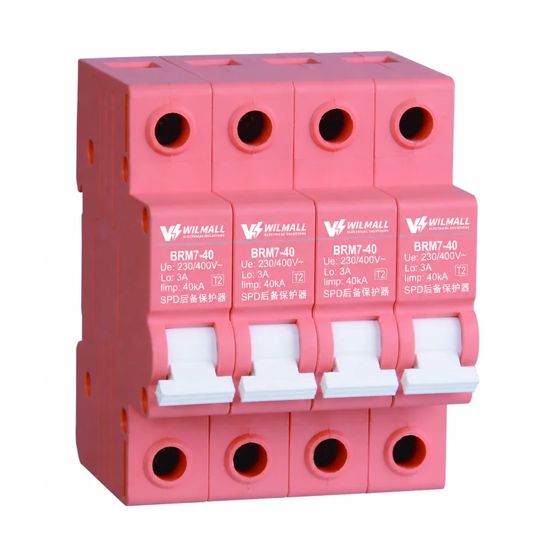
The backup protector has to match the surge device it is guarding, and the range covers both stages of a coordinated scheme. The T1 version shown here is the companion for a Type 1 entrance device: it carries a 15 kA impulse marking and sits ahead of the BRM8 Type 1 surge protector. The T2 version, marked 40 kA, is the companion for the BRM7-40Y Type 2 module and is supplied in a red housing so that the two are not mixed up on site.
Matching matters in both directions. Fitting a T2 backup ahead of a Type 1 device leaves the entrance position under-protected, and fitting a T1 backup ahead of a Type 2 module is simply money spent on capability that will never be used. The rule is to match the backup to the impulse class of the device it protects. Both versions sit in the same surge protection range, so a mixed order for a two-stage scheme ships as one consignment.
The Label on the Front
Ue is the rated working voltage, quoted here as 230/400 V for a three-phase four-wire system. The 3 A figure is the rated current of the device, which is deliberately small because the normal current through a surge branch is zero; the rating describes the fault current path, not a load. The T1 or T2 marking in the box identifies which surge class the unit is intended to accompany, and the Iimp value states the impulse it will pass without operating.
Four poles are provided so that the backup can be connected in series with each pole of a four-pole surge device without leaving one path unprotected. A three-pole backup in front of a four-pole protector leaves the neutral path with no short-circuit protection, which is exactly the path that carries current in a TT system during a phase-to-neutral event.
Wiring an SPD Backup Protector Into the Board
The SPD backup protector mounts on a 35 mm DIN rail and accepts conductors from 6 to 25 mm², matching the cable sizes normally used at the surge branch. It is installed immediately upstream of the surge device, in the same enclosure, with the shortest practical conductor run between the two. Long leads between the backup and the surge protector add impedance to the branch and raise the voltage that appears at the protected equipment during an event.
The ambient range of −25 to +60 °C and the IP20 enclosure mean the device is intended for indoor panel mounting. Where the surge branch is in an outdoor cabinet, that cabinet has to provide the environmental protection; the module itself is not weatherproof.
Maintenance After a Fault
After the backup has operated, the surge device behind it should be inspected as well. A fault severe enough to open the backup has usually been severe enough to affect the varistor stack, and replacing one without checking the other leads to a repeat visit. The status window on the surge module tells you whether the cartridge survived; if it has gone red, the cartridge is replaced and the backup is reset. Keeping a spare cartridge and a spare backup on the shelf turns that into a single visit rather than two.
Supply for Panel Builders and Distributors
Every SPD backup protector in this range is assembled and tested in our own plant, and the front cover can be printed with a distributor’s own brand for volume quantities. Both stage versions are produced on the same line, so a mixed order for T1 and T2 backups can ship together with a single packing list.
For BRHB-T1 price, datasheet, matching recommendation or OEM supply information, contact our sales team with the surge device model and the board rating.
PERGUNTAS FREQUENTES
Why can a miniature circuit breaker not do this job?
Because it is designed around a load. Fitted in a surge branch it can treat the impulse as an overload and open during a storm, or it can ride through the impulse and then fail to clear quickly when the varistor fails into a short circuit. Either way the board ends up in the wrong state at the wrong moment.
Which version matches which surge device?
Match the backup to the impulse class of the device it guards. The T1 version, marked 15 kA, is the companion for a Type 1 entrance device. The T2 version, marked 40 kA and supplied in a red housing, is the companion for a Type 2 module. Mixing them either under-protects the position or wastes capability.
What has to be done after the backup has operated?
Inspect the surge device behind it as well. A fault large enough to open the backup has usually affected the varistor stack, so check the status window on the module and replace the cartridge if it has gone red, then reset the backup. Keeping both spares on the shelf makes that a single visit.
Is a 3 A rating not far too small?
The normal current through a surge branch is zero, so the rating does not describe a load. It describes the fault path, and a small rating is what allows the device to react to a failed varistor without being sized for current that will never flow.
Why does it need four poles?
Because the surge device it protects has four poles. A three-pole backup leaves the neutral path without short-circuit protection, and in a TT system the neutral is exactly the path that carries current during a phase-to-neutral event.
Can one backup serve two surge devices?
No. It is connected in series ahead of one device, one pole per pole, and the impedance of a shared arrangement would also raise the voltage that appears at the protected equipment. Each surge device gets its own backup in its own branch.
Request Quote
Tell us your specifications, quantity, or application scenario and we will reply with a tailored quote.