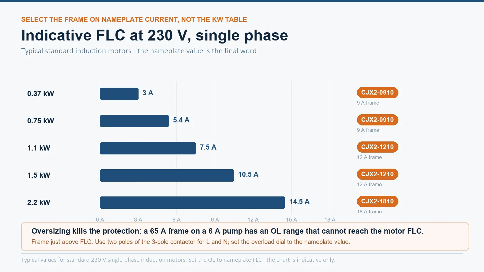
A single-phase 230 V pump still needs a contactor whenever a float switch, pressure switch or remote control starts it automatically. Size the contactor on the motor’s nameplate full-load current at 230 V (about 3 A for 0.37 kW up to about 14.5 A for 2.2 kW), switch both line and neutral with two poles of the contactor, leave the run capacitor and start winding wired exactly as the motor nameplate diagram shows, and set the overload relay to nameplate FLC — not to the cable or breaker rating.
Most “dead pump” calls in the field trace back to the starter panel, not the pump: a contactor sized off the kW table instead of the nameplate, an overload relay set wrong, or a capacitor circuit that was rewired by guesswork. This article covers the complete wiring chain for a 230 V single-phase pump — contactor selection, the C/S/R terminal box, power and control circuits, and the overload relay — with the numbers to put on the drawing.
Why a 230 V Pump Still Needs a Contactor
A single-phase pump motor drawing 5–15 A cannot be switched reliably by a light switch or a float switch contact. Three reasons, in order of how often they burn people:
- Arc energy. An inductive motor load draws locked-rotor current at make and breaks a load at speed. A manual switch contact pits and welds within weeks of daily cycling; a contactor’s arcing chamber is built for exactly this duty.
- Automatic control. Float switches, pressure switches and level controllers handle milliamps-to-a-few-amps at low voltage. They belong in the control circuit feeding the coil (A1/A2), never in the motor’s power path — putting a float switch in the power circuit is one of the most common wiring faults we hear about from pump installers.
- Overload coordination. A contactor plus thermal overload relay forms a motor starter: the contactor switches, the overload protects the winding. Neither task alone justifies the device; together they are the minimum a pump panel needs.
Know Your Motor Type First: PSC, Capacitor-Start and CSCR
The contactor wiring does not change between these types — the contactor always switches the supply to the motor. But what sits in the terminal box does, and misidentifying the type is the root of most capacitor-related faults.
| Motor type | Windings in circuit at run | Capacitor | How the start circuit switches out | Typical pumps |
|---|---|---|---|---|
| PSC (permanent split capacitor) | Main + auxiliary, both permanent | Run capacitor only, permanently in circuit | Never switches out | Small circulator and booster pumps, fans |
| Capacitor-start (CS) | Main only at run | Start capacitor only | Centrifugal switch at ~75 % speed (open motors) or potential relay (submersibles) | Surface jet pumps, small pressure pumps |
| CSCR (capacitor-start, capacitor-run) | Main + auxiliary | Start capacitor in series with potential relay contact, in parallel with run capacitor | Start cap dropped at ~75 % speed; run cap stays | Larger single-phase pumps, 1.1 kW+ submersibles |
Note the submersible case: a Franklin-type 4-inch 230 V 50 Hz motor table shows 0.25–0.75 kW units with a start capacitor and no run capacitor, while 1.1 kW units add a small run capacitor (10–35 µF) and much larger start capacitors (105–324 µF). The start capacitor delivers a torque burst and must be removed at speed; leaving it in circuit burns the start winding in seconds to minutes.
Reading the Terminal Box: C, S, R and the Capacitor Connections
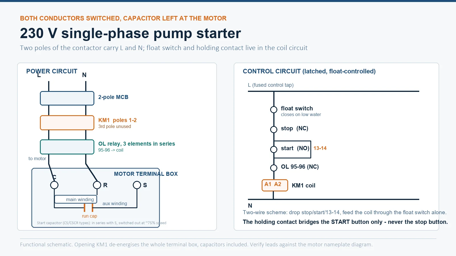
Single-phase motor terminal boxes are marked C (common), R (run winding) and S (start/auxiliary winding). The supply from the contactor lands on C and R; the run capacitor bridges between C and S (in series with the auxiliary winding). Three-wire submersible motors use coloured leads — typically main (brown), start (brown/black), common (yellow) — but colour conventions vary by manufacturer, so verify continuity against the motor datasheet instead of trusting colours.
Two rules that prevent most terminal-box errors:
- The capacitor circuit is switched with the motor, by the same contactor. Never leave the capacitor circuit energized while the contactor is open — an auxiliary winding fed without the main winding energized overheats and fails.
- Reversing rotation on a single-phase motor means swapping the two start-winding leads (or the marked rotation plug), not swapping the incoming line and neutral — swapping L and N does nothing to direction on a single-phase motor.
Sizing the Contactor: FLC at 230 V, Not kW Tables Alone
Use the nameplate full-load current as the final word; the indicative chart below (typical values for standard 230 V single-phase induction motors) is for the drawing stage.
| Motor output (kW) | ≈ FLC at 230 V (A) | Contactor frame (AC-3 Ie) | Typical pump duty |
|---|---|---|---|
| 0.37 | 3.0 | 9 A (e.g. CJX2-0910) | Small circulator / sump |
| 0.75 | 5.4 | 9 A (CJX2-0910) | Domestic booster |
| 1.1 | 7.5 | 9–12 A (CJX2-1210) | Small irrigation / 4″ submersible |
| 1.5 | 10.5 | 12 A (CJX2-1210) | Farm / light commercial pump |
| 2.2 | 14.5 | 18 A (CJX2-1810) | Large jet / 4″ high-flow |
Three selection notes that matter on single phase:
- Use two poles of a three-pole contactor. Wire line through one pole and neutral through the second so both conductors are switched together; the third pole stays unused. Switching both L and N is the standard safe practice on 230 V pump circuits and matches the double-pole MCB upstream. See our 1-pole vs 2-pole comparison for when a single pole is acceptable.
- Single-phase switching is gentler than three-phase. There is no phase-to-phase recovery voltage across a single contact gap at 230 V, so a frame selected on current at 230 V single-phase duty has ample margin — but still select on AC-3 current, because the make is onto locked-rotor current like any motor.
- Do not oversize “for safety”. A 65 A frame on a 6 A pump has an overload relay range that cannot reach the motor FLC, so the protection stops working. Frame current should sit just above FLC, not ten times above.
Wiring the Power Circuit, Terminal by Terminal
- Incoming supply — line and neutral to a double-pole MCB (or isolator) sized on motor FLC with starting margin; add a 30 mA RCD for wet-environment shock protection. Earth lands on the earth bar first, never switched or fused.
- Contactor line side — MCB load-side line to contactor pole 1 (L1), neutral to pole 2 (L2/T2 position on the same frame).
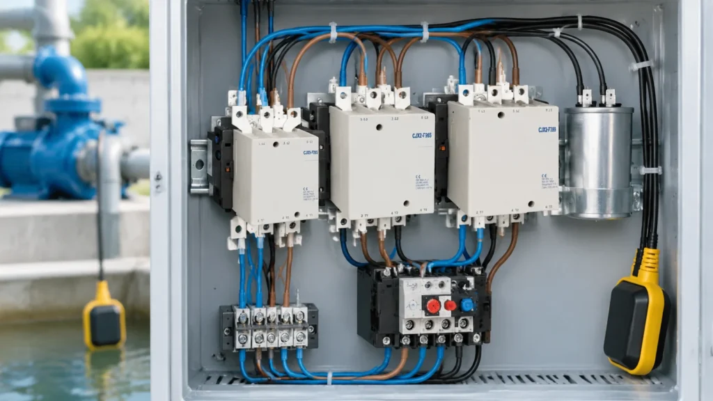
- Overload relay — contactor load side into the OL relay line terminals. For a three-pole thermal relay on single phase, pass the same current through all three poles in series (L → pole 1 → pole 2 → pole 3 → motor) so every heating element sees full current and trips correctly; alternatively fit a dedicated single-phase overload relay.
- Motor cable — OL relay output to the motor terminal box: switched line to C, return through R. Earth core to the motor frame stud. Run capacitor between C and S (per the motor diagram), start capacitor + centrifugal switch or potential relay where the motor type requires it.
- Capacitor ratings — match the nameplate microfarad value exactly; run capacitors are typically 30–50 µF per kW as a rough sizing guide, and capacitor voltage rating must exceed supply voltage by 15–20 % (370 V or 440 V rated parts on a 230 V system).
Wiring the Control Circuit: Float Switch, Pressure Switch and the Holding Contact
Two standard control schemes cover almost every pump installation:
- Two-wire (direct) control — the float switch or pressure switch sits in series with the coil (control fuse → float switch → A1; A2 to neutral). The pump starts and stops with the sensor, no start button, no holding contact. Simple, but the pump restarts automatically after any power interruption — correct for a sump, hazardous for a flooded area.
- Three-wire (latched) control — stop button (NC), start button (NO) and the contactor’s own NO auxiliary contact (13–14) in parallel with the start button, then the overload relay’s NC contact (95–96), then A1. The pump latches on and stays on until stop or trip. This is the scheme that survives power dips safely, because it drops out on supply failure and needs a deliberate restart.
The float switch goes in series in the coil circuit in both schemes — it stops the pump at full tank and allows restart at low level. For well and borehole pumps, add dry-run protection (a level probe relay or current-sensing relay) so an empty well does not cook the mechanical seal.
A wiring fault worth naming because it is so common: the holding contact must bridge the start button only. Wired in parallel with the stop button instead, the contactor chatters or fails to latch — the symptom looks like a bad coil but is a two-minute terminal swap to fix. The full coil-circuit anatomy is in our contactor wiring guide.
The Overload Relay: Setting, Placement and the Single-Phase Catch
Set the dial to the motor nameplate full-load current — not the cable rating, not the breaker rating, not the kW-table estimate. The three-phase charts and worked examples in our starter and overload sizing guide follow the same logic; only the phase arrangement differs here.
| Item | Rule for a single-phase pump |
|---|---|
| Setting value | Nameplate FLC (e.g. 10.5 A for a 1.5 kW pump at 230 V) |
| Relay type | Dedicated single-phase relay, or 3-pole thermal relay with poles in series so all elements carry full current |
| Placement | Between contactor and motor, in the power circuit; its 95–96 NC contact drops the coil |
| Reset mode | Manual for pumps that must not auto-restart into a fault; auto only where unattended restart is acceptable |
The catch most installers miss: a three-pole thermal relay with current through only one or two poles will not trip at the right point, because the bimetal elements never see balanced current. That is why the series-through-all-poles arrangement (or a true single-phase relay) is the correct answer, not an optional refinement.
Capacitor Problems Masquerading as Contactor Problems
Before blaming the contactor for a pump that “won’t start”, check the capacitor circuit — it fails far more often, and the symptoms overlap:
| Symptom | Usual cause | Check |
|---|---|---|
| Motor hums, does not turn, breaker trips | Open or swollen start/run capacitor; centrifugal switch not closing at rest | Capacitance meter on the capacitor; continuity through the centrifugal switch |
| Runs, then trips the overload after minutes | Run capacitor degraded (below nameplate µF), or start winding left energized by a stuck switch | Compare measured µF with nameplate; listen for the switch click at ~75 % speed |
| Contactor chatters | Control-side problem, not the capacitor: low coil voltage, bad holding contact wiring, failing float switch contact | Measure coil voltage under load; see our buzzing diagnosis |
| Contactor welded closed | Float or pressure switch placed in the power circuit, or a contactor frame far too small for FLC | Inspect switching arrangement; verify frame current vs nameplate FLC |
Commissioning Checks Before You Walk Away
- Insulation resistance between each motor lead and earth in the hundreds of megohms on a 500 V tester — mandatory for submersibles before the cable goes in the water.
- Continuity of the control chain: fuse → float switch → stop → start → OL 95–96 → A1, A2 to neutral.
- Start the pump uncoupled (or with the well valve throttled): confirm clean pull-in, no chatter, centrifugal switch click at speed.
- Measure running current on each conductor and compare to nameplate; a running current well above FLC means low supply voltage, a failing capacitor, or a mechanical bind.
- Verify the overload trips by pressing its test button — the contactor must drop out.
- Confirm the holding contact drops the pump on stop, and that a power dip does not leave a three-wire installation running unattended.
Perguntas frequentes
Can I use a 3-pole contactor for a single-phase pump?
Yes — that is the normal practice. Use two poles to switch line and neutral together and leave the third unused. For the overload relay, either fit a dedicated single-phase relay or pass the current through all three relay poles in series so every heating element sees full current.
What size contactor for a 1.5 kW 230 V single-phase pump?
A 12 A frame (e.g. CJX2-1210) covers the typical 10.5 A FLC with margin. Always confirm against the nameplate FLC — two motors of the same kW can differ — and set the overload dial to that nameplate value.
Does the contactor switch the run capacitor?
Indirectly, yes. The capacitor stays wired to the motor’s auxiliary winding, so opening the contactor de-energizes the whole terminal box including the capacitor circuit. The capacitor itself is never wired through a separate switch — it must never be energized while the motor is stopped.
Why does my pump contactor drop out when the float switch is fine?
Check the overload relay 95–96 contact (a trip holds it open), then the coil voltage under load. A control transformer or long control cable sagging below 85 % of coil rated voltage causes intermittent drop-outs that look like sensor faults.
Can I start a single-phase pump directly with the float switch, no contactor?
Not for anything above a fractional-kilowatt motor. The float contact cannot safely make and break motor current, and you lose overload protection entirely. Put the float switch in the coil circuit and let the contactor carry the load — that is what it is for.
Need contactors sized for pump duty? The CJX2 series AC contactors from 9 A to 95 A frames cover 0.37–2.2 kW single-phase pumps and the full three-phase range, and for pump-panel retrofits our HVAC contactor replacement guide covers the dedicated-purpose equivalents. Send us the motor nameplate and we will confirm the frame, coil voltage and overload range.