How to Wire a Contactor: Power, Coil, Auxiliary & Overload Wiring
Published: Author: Lisa
Understanding Contactor Terminal Markings
Before wiring any contactor, you need to read its terminal markings correctly. Every contactor follows standardized numbering conventions that tell you exactly where each wire goes. Getting these wrong can short your control circuit, burn the coil, or fail to energize the motor at all.
Terminal
Função
Notes
L1, L2, L3
Line (power input)
Three-phase supply from breaker
T1, T2, T3
Load (power output)
Motor or downstream load
A1, A2
Coil terminals
Control voltage input
13 → 14
Auxiliary NO contact
Normally open; closes when coil energizes
11 → 12
Auxiliary NC contact
Normally closed; opens when coil energizes
95 → 96
Overload relay NC
Opens on overload trip
97 → 98
Overload relay NO
Closes on overload trip (for alarm)
The L/T terminals carry the full motor current, while A1/A2 and the auxiliary contacts handle only control-level current. Understanding this distinction is the first step to a safe and correct AC contactor installation.
The power circuit is the heavy-current path that runs from your supply breaker through the contactor’s main contacts to the motor. Here is how to wire it correctly:
Bring three-phase supply to L1, L2, L3. Run appropriately sized cables from your molded case circuit breaker (MCCB) to the top terminals. For a typical 7.5 kW motor at 400 V, you would use 6 mm² copper conductors.
Connect motor leads to T1, T2, T3. The output side feeds the motor. If an overload relay is used, the wiring passes through it between T1-T3 and the motor.
Verify phase sequence. Incorrect phase order can cause the motor to run in reverse. Swap any two L-side terminals to correct direction.
Torque every terminal. Loose power connections cause heat buildup and arc damage. Follow the manufacturer’s torque spec—typically 2.0–2.8 Nm for frame sizes up to S2.
For single-phase loads, use L1 and L2 (or L1 and N, depending on the contactor design) for input and T1/T2 for output. Never use L3/T3 for single-phase applications unless the datasheet explicitly allows it.
Coil Control Circuit Wiring (A1 and A2)
The coil is the electromagnet that pulls the main contacts closed. It has two terminals: A1 (positive or line side) and A2 (negative or neutral side). The control voltage must match the coil’s rated voltage—this is the most common mistake we see in the field.
Before connecting, check the coil voltage rating printed on the contactor or its datasheet. Common ratings include 24 V AC/DC, 230 V AC, and 400 V AC. Supplying 230 V to a 24 V coil will destroy it instantly. For guidance on AC vs DC coil selection, the key differences in arc suppression and control circuit design matter significantly.
AC coils: Most common in industrial panels. A1 receives the control supply (e.g., from a start button), A2 connects to neutral or the control circuit return.
DC coils: Used in battery systems or PLC-controlled circuits. A1 is positive, A2 is negative. Polarity must be observed for coils with built-in flyback diodes.
Always run the control circuit wiring through the overload relay’s NC contact (95-96) so that the coil drops out automatically when an overload occurs.
Auxiliary Contact Wiring for Control Logic
Auxiliary contacts handle the control logic—they do not carry motor current. They let you build holding circuits, interlocks, status signals, and PLC inputs.
Seal-In (Holding) Circuit with NO Contact (13-14)
The most common use of the NO auxiliary contact is the seal-in or holding circuit. When you press the start button, the coil energizes, and the NO contact (13-14) closes in parallel with the start button. This keeps the coil energized after you release the button.
Interlocking with NC Contact (11-12)
In reversing starter applications, the NC auxiliary contact from one contactor is wired in series with the coil of the other contactor. This ensures that the forward and reverse contactors can never be energized simultaneously, preventing a phase-to-phase short circuit.
Overload Relay Wiring
The overload relay mounts directly beneath the contactor in most modular designs (like the 3TF series contactor). It monitors motor current and trips if the load exceeds the set threshold for too long.
Here is how to wire the overload relay into your circuit:
Power path: Motor leads pass through the overload relay’s current sensors (T1, T2, T3 connections on the relay).
Control trip (95-96): Wire these NC contacts in series with the contactor coil (A2 side). When the relay trips, the contact opens and drops the coil, stopping the motor.
Alarm signal (97-98): These NO contacts close on trip and can be wired to a pilot lamp, buzzer, or PLC digital input to signal the overload event.
Set the current dial: Adjust the overload relay’s current setting to match the motor’s full-load current (FLC). This is critical—too high and the motor burns, too low and it nuisance-trips.
The three-wire control circuit is the standard start-stop arrangement used in nearly every industrial motor application. Here is the complete wiring sequence:
Stop button (NC): Wired in series with the control supply. It is normally closed, so current flows until pressed.
Start button (NO): Wired in parallel with the seal-in contact (13-14). Pressing it energizes the coil.
Seal-in contact (13-14 NO): Closes when the coil energizes, maintaining current flow after the start button is released.
Overload NC (95-96): Wired in series after the stop button. Opens on overload trip to break the circuit.
Coil (A1-A2): The final element in the series. A1 receives the control supply, A2 returns to neutral.
The current path is: Supply → Stop (NC) → Overload (NC) → [Start (NO) ∥ Seal-in (NO)] → Coil A1 → Coil A2 → Neutral. Pressing stop opens the circuit; pressing start closes it; the seal-in keeps it closed.
If you are building a control panel, keep in mind the difference between a contactor and a relay: contactors handle higher current and motor loads, while relays are suited for lower-power switching and signal-level applications.
Safety Best Practices for Contactor Wiring
Disconnect and lock out the main supply before touching any terminal. Never wire a live panel.
Verify dead with a multimeter. Check L1-L2, L2-L3, L1-L3, and each phase to neutral before starting work.
Use the correct wire size for the motor’s full-load current. Undersized wires overheat and can cause fires.
Apply proper terminal torque. Check the contactor datasheet for the torque specification and use a calibrated screwdriver.
Use a proper enclosure. The panel should meet the required IP or NEMA rating for the environment—dust, water, and corrosive atmospheres all degrade electrical connections over time.
Label every wire. Use ferrule terminals and wire markers for L1, L2, L3, T1, T2, T3, A1, A2, and control-circuit wires. This saves hours during future maintenance.
Common Contactor Wiring Mistakes to Avoid
Mistake
Consequence
Fix
Wrong coil voltage (e.g., 230 V applied to 24 V coil)
Coil burns out instantly
Always verify coil voltage rating before connecting
Missing overload relay in control circuit
Motor runs unprotected; burns on sustained overload
Always wire 95-96 NC in series with coil
Seal-in contact wired to NC (11-12) instead of NO (13-14)
Contactor chatters or fails to hold
Use the NO auxiliary contact for holding circuits
Loose power terminals
Heat damage, arcing, eventual failure
Torque to spec; re-check after thermal cycling
Control wiring mixed with power wiring in same conduit
EMI interference, signal noise
Route control wires in separate conduit or shielded channel
[[IMAGE: Contactor with overload relay assembly showing complete wiring from three-phase supply through main contacts, overload relay, and motor terminals]]
PERGUNTAS FREQUENTES
What voltage does a contactor coil use?
Contactor coils are available in 24 V AC/DC, 48 V DC, 110 V AC, 230 V AC, and 400 V AC ratings. You must match the coil’s rated voltage to your control circuit supply. The voltage is printed on the coil housing or stated in the datasheet.
Can I use a 230 V coil on a 24 V supply?
No. A 230 V coil connected to 24 V will not generate enough magnetic force to pull in the armature—the contacts will not close. Conversely, a 24 V coil on 230 V will burn out immediately. Always match the supply to the coil rating.
What is the difference between NO and NC auxiliary contacts?
NO (normally open) contacts are open when the coil is de-energized and close when it energizes. NC (normally closed) contacts are closed when de-energized and open when energized. NO contacts (13-14) are used for seal-in circuits; NC contacts (11-12) are used for interlocks.
How do I wire a contactor with an overload relay?
Mount the overload relay below the contactor. The motor output from T1, T2, T3 passes through the relay’s current sensors. Wire the relay’s NC contact (95-96) in series with the coil’s A2 terminal so that a trip automatically breaks the control circuit and de-energizes the contactor.
Do I need a start button for a contactor?
For a three-wire control circuit, yes—you need a momentary NO start button and a momentary NC stop button. The start button energizes the coil; the NO auxiliary contact (13-14) holds it in. For a two-wire control (e.g., float switch or thermostat), the control device itself provides the maintaining signal.
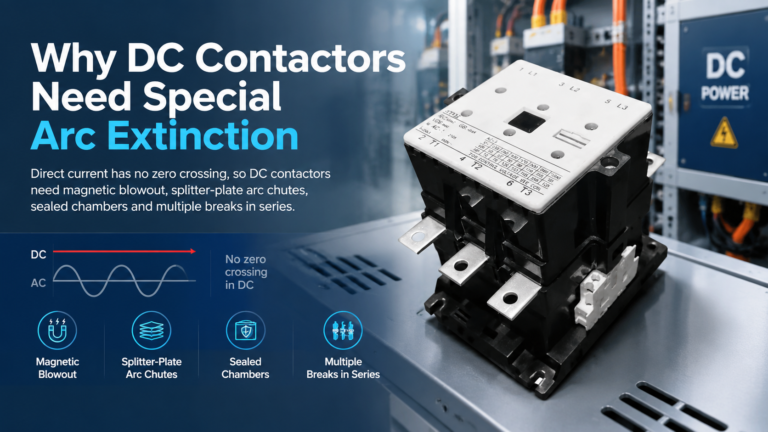
DC contactors need special arc extinction because DC current has no natural zero crossing. See how magnetic blowout, arc chutes and series breaks kill a DC arc — and how to specify one correctly.
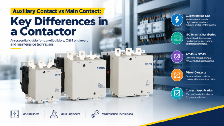
Main contacts carry the motor current; auxiliary contacts carry control signals. Learn the real rating gap, IEC terminal codes, and how to spec both correctly.
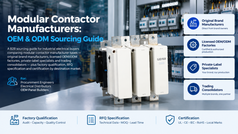
A sourcing guide to modular contactor manufacturers: match the four supplier archetypes, qualify any factory with a nine-point framework, and send an RFQ that gets comparable quotations.