


Descrição
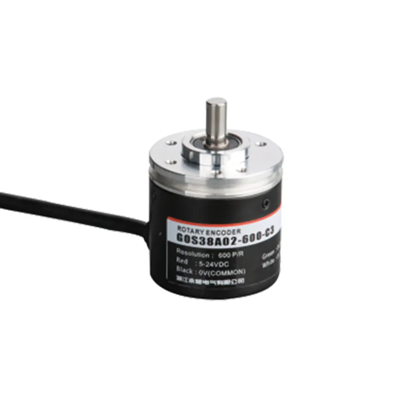
O codificador rotativo incremental GOS38A02 foi projetado para o controle preciso de movimentos em aplicações de automação industrial. Com um diâmetro compacto de 38 mm e eixo semi-oco, ele fornece feedback preciso de posição e velocidade com resoluções de até 10.000 pulsos por revolução. Sua construção robusta com classificação IP65 garante um desempenho confiável em ambientes adversos. Compatível com vários PLCs e sistemas de controle, o GOS38A02 oferece sinais de saída versáteis, incluindo coletor aberto, push-pull e driver de linha, garantindo uma integração perfeita em máquinas de transporte, robótica, CNC e de embalagem.
Principais recursos
Codificador rotativo óptico incremental com opções de alta resolução de 100 a 10.000 PPR
Projeto de eixo semi-oco (normalmente 8 mm de diâmetro) para instalação direta do motor e fácil acoplamento
O invólucro com classificação IP65 protege contra a entrada de poeira e água, proporcionando durabilidade industrial
Ampla faixa de tensão de entrada CC de 5 a 24V para compatibilidade flexível do sistema
Vários tipos de sinal de saída: coletor aberto (NPN), push-pull complementar e sinais diferenciais do driver de linha de 5V
Circuito anti-interferência para saída de sinal estável e resistente a ruídos
Diâmetro externo compacto de 38 mm, facilitando a integração em montagens mecânicas apertadas
Opções de cabos longos com luvas de proteção de borracha disponíveis
Vantagens do produto
Medição de alta resolução que permite o controle preciso da velocidade e da posição
O eixo semi-oco facilita a instalação e o alinhamento do eixo
A robusta proteção IP65 aumenta a longevidade do codificador em ambientes difíceis
As saídas versáteis suportam uma ampla gama de aplicações de controle industrial
A imunidade aprimorada a ruídos de sinal garante feedback consistente em ambientes com ruídos elétricos
Tamanho compacto que economiza espaço, adequado para aplicações com espaço de instalação limitado
Modelo e significado do produto
| G | 0 | S | 38 | □ | A | 02 | 2000 | C | 3 | 2M | |||
| Categoria de produto | Tipo de produto | Forma de eixo principal | Contorno de produto | Tamanho do eixo principal, furo do eixo | Saída e formulário de selagem | Esboço estrutura | Resolução | Formulário de saída | Sinal de saída | Cabo | |||
| G:incremental tipo | 0:megneto- eletricidade | S: eixo sólido | 38:φ38mm | □:φ6mm | A: saída lateral de borracha | 02:2esboço estrutura2 | 10,20,50,60, 100,200,360, 400,500,600, 800,1000, 1024,1200, 2000,2048, 2500,3000, 3600,5000 | C: saída de coletor aberto F: saída complementar T:saída push pull L:Saída de acionamento de 5V A:Saída de acionamento de 24V | 1:fase Asignal 2:sinal de fase AB 3:fase do sinal ABZ 4:fase Sinal ABA/B/ 5:fase do sinal ABZA/B/Z/ | Padrão 2m linha, para não 2m, A rotulagem é suficiente |
Tabela de fiação
| Cor da linha | Sinal de saída C/F | – | Cor da linha | Sinal de saída |
| marrom | VCC | marrom | VCC | |
| azul | GND | |||
| azul | GND | |||
| preto | Uma fase | |||
| preto | Uma fase | branco | Fase B | |
| laranja | Fase Z | |||
| branco | Fase B | |||
| preto vermelho | Fase | |||
| laranja | Fase Z | branco vermelho | Fase B | |
| vermelho alaranjado | Fase Z | |||
| escudo | F -G | |||
| escudo | F -G |
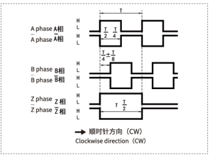
Diferença de fase de saída
saída complementar/coletor NPN saída de circuito aberto/saída push pull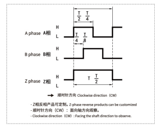
saída de acionamento de linha longa
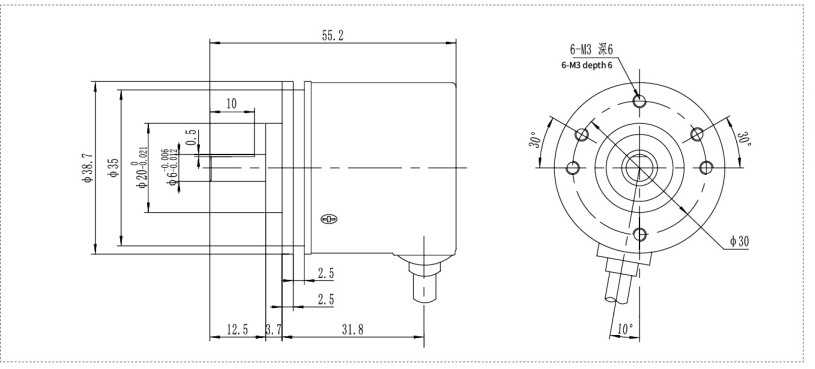
Desenhos mecânicos (mm)
Product Parameter
1. Model / Series: GOS38A02
2. Product Type: Motor Shaft Encoder
3. Function: Speed, position, and direction feedback
4. Applications: Motors, CNC machines, conveyors, robotics, automation systems
Meta Description
Buy GOS38A02 Motor Shaft Encoder from a trusted supplier, manufacturer and factory. OEM/ODM custom service at wholesale price.
Product Details
The GOS38A02 Motor Shaft Encoder Supplier product is a rotary feedback device designed to convert motor shaft rotation into accurate electrical pulse signals. It helps industrial automation systems monitor speed, position, direction, and motion control status with stable performance.
This motor shaft encoder is widely used in motors, CNC machines, conveyors, packaging equipment, robotics, elevators, textile machinery, printing machines, and industrial control panels. It is suitable for industrial users, commercial users, electrical contractors, distributors, and bulk B2B procurement buyers.
As a professional GOS38A02 Motor Shaft Encoder Supplier, manufacturer, wholesaler, distributor, factory, and OEM/ODM partner, we provide stable quality, custom specifications, bulk supply, and competitive wholesale price solutions.
Key features include compact GOS38A02 design, accurate rotary feedback, stable signal output, fast response, easy installation, durable construction, and long service life for demanding industrial applications.
Cenários de aplicativos
Medição de velocidade e posição de motores industriais para automação
Máquinas CNC para posicionamento preciso de ferramentas e feedback de rotação
Controle de velocidade e posição da correia transportadora em linhas de embalagem
Robótica que requer feedback preciso de juntas e eixos
Máquinas de impressão para sincronizar os movimentos do rolo e da folha
Linhas de montagem automatizadas que exigem feedback rotativo de alta confiabilidade
Instalação e manutenção
Verifique o diâmetro do eixo e combine-o com o eixo do codificador semi-oco de 8 mm para obter um encaixe seguro.
Alinhe os eixos cuidadosamente para evitar estresse mecânico e garantir um feedback preciso. Recomenda-se o uso de acoplamento flexível.
Fixe o codificador firmemente com parafusos de montagem para evitar vibrações ou movimentos de rotação.
Conecte a fonte de alimentação entre 5 e 24 VCC e conecte os sinais de saída de acordo com a interface necessária (consulte os diagramas de fiação).
Use cabos de par trançado blindados sempre que possível para minimizar a interferência eletromagnética.
Mantenha o compartimento do codificador limpo e livre de acúmulo de poeira.
Inspecione periodicamente as conexões elétricas quanto a aperto e sinais de desgaste.
Substitua o codificador imediatamente se a integridade do sinal se degradar ou se ocorrerem danos mecânicos.
PERGUNTAS FREQUENTES
Q1: What is the GOS38A02 Motor Shaft Encoder used for?
It is used for motor speed measurement, position feedback, direction detection, and motion control in automation systems.
Q2: Are you a GOS38A02 Motor Shaft Encoder Supplier and manufacturer?
Yes, we are a factory supplier supporting wholesalers, distributors, electrical contractors, and industrial users.
Q3: Can the GOS38A02 Motor Shaft Encoder be customized?
Yes, OEM/ODM and custom options are available for shaft type, resolution, cable length, output signal, voltage, and connector type.
Q4: Do you offer wholesale price for distributors?
Yes, we provide competitive wholesale price options for distributors, wholesalers, and bulk B2B buyers.
Q5: Where can this motor shaft encoder be applied?
It is suitable for motors, CNC machines, conveyors, packaging equipment, robotics, elevators, and industrial control systems.
Request Quote
Tell us your specifications, quantity, or application scenario and we will reply with a tailored quote.


