A contactor that will not open is rarely a contactor that was too small for its running current. It is almost always a contactor that was closed into a current it was never meant to make. Welding machines, capacitor banks and transformer primaries present the same problem in three different shapes: a burst of current that arrives in the first few milliseconds, while the contacts are still bouncing against each other. By the time the running current settles to something the nameplate can carry, the damage is already done.
This guide explains the three mechanisms that fuse AC contactor contacts shut on welding and high-inrush loads, how to calculate whether a given frame can survive the making current, and what to change when it cannot. It is written for the people who specify the device, not for the people who sell it.
Quick Answer: Why Contacts Weld on Welding and High-Inrush Loads
Contactor contacts weld for three reasons, and only one of them is about steady-state current:
- A making weld during closing bounce. The armature slams home, the contacts touch, bounce apart, and touch again one to five times within 0.5 to 3 milliseconds. Every bounce restrikes an arc into a contact surface that has just been softened by the previous one.
- An inrush above the making capacity. The peak current in the first half-cycle exceeds what the contactor can close on. The magnetic force of that peak is strong enough to blow the contacts apart again while the coil is still energised — and the arc that follows fluidises the silver.
- A breaking weld from a magnet system that releases too slowly. A weak coil, an undersized control transformer or the wrong surge suppressor makes the contacts separate slowly, or re-close briefly during the break. A weld that would normally be forced open by the contact springs never gets broken.
The practical consequence: sizing a contactor for a welding machine by matching its AC-3 current rating to the transformer’s primary current is the wrong calculation. The frame has to be chosen on thermal current, and then checked against making capacity. Those two numbers rarely point at the same device.
What a Welding Load Actually Looks Like
A resistance welding machine does not behave like a motor. The transformer primary is switched on and off once per weld, often hundreds of times per shift, and the switching instant is not synchronised with the supply waveform. Three things follow from that:
- The first half-cycle is asymmetric. Closing at a random point on the sine wave leaves a DC offset in the transformer flux, so the first peak can be substantially higher than the steady-state magnetising current. Phase-angle controlled welding controls make this worse, because they fire the thyristors part-way up the wave by design.
- The duty is intermittent but brutal. The RMS current over a shift may look modest because the arc time is short, while each individual closure is a hard make on a saturated core.
- There is no overload relay to catch it. Welding transformer primaries are usually protected by fuses or a dedicated breaker, not a thermal overload. Nothing in the circuit is watching the contactor’s contact erosion.
Capacitor banks and transformer primaries are close cousins. A discharged capacitor looks like a short circuit for the first few microseconds of charging, so the closing current is limited only by the loop impedance. An energised transformer presents a saturated core for the first few cycles. In both cases the contactor is asked to close on something much larger than the load it will carry a second later — which is exactly the duty that AC-6a and AC-6b utilisation categories were created to describe.
Mechanism One: Closing Bounce Restrikes the Arc
Bounce is the part of the closing event that catalogues never mention. When the coil is energised, the armature accelerates for roughly 10 to 30 milliseconds and then hits the magnet core. The moving contact carrier does not stop with it. It rebounds — typically one to five times, over a window of 0.5 to 3 milliseconds — before the contact pressure settles.
During each rebound the gap is small, the voltage across it is at full supply level, and an arc strikes immediately. The contact resistance during that bounce is not the milliohm figure you would measure on a closed contact; it rises by two orders of magnitude as the surfaces separate. Multiply that by an inrush in the kiloamp range and the instantaneous power at the contact spot reaches hundreds of kilowatts for a fraction of a millisecond. That is enough to melt a local pool of silver alloy. If the surfaces are still moving when the pool solidifies, they fuse.
This is why the same contactor that survives a resistive heater load for a million operations can weld shut on a welding transformer in a few thousand. The heater closes into a current that is already at its final value; the welding transformer closes into a current that is ten times larger, at the exact moment the contacts are least able to carry it.
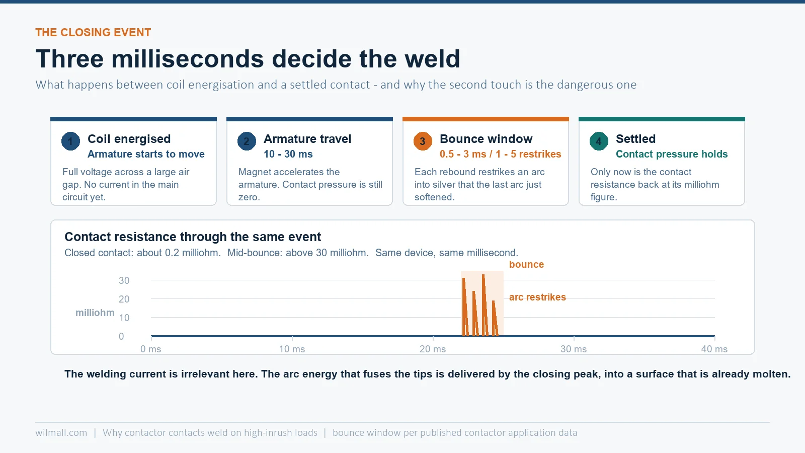
Two variables decide how bad the bounce is. The first is contact pressure, which is a design property of the frame. The second is how hard the armature hits — and that is a function of coil voltage. A coil held at 85 percent of its rated voltage pulls in noticeably more slowly than one at 100 percent, and the softer landing shows up as longer bounce. This is the mechanism behind the IEC 60947-4-1 requirement that AC coils must pick up between 85 and 110 percent of rated control supply voltage; below that window, bounce duration roughly triples and electrical life falls to about a third of the rated figure. The same coil data is set out in more detail in our guide to coil inrush and sealed VA.
Mechanism Two: Inrush Above the Making Capacity
Every contactor has a making capacity, and it is not the same number as its rated operational current. The conventional figure used across IEC 60947-4-1 devices is ten times the AC-3 rated current, expressed as an RMS value — which means the peak it must survive is that figure multiplied by the square root of two.
In round numbers: a contactor rated 115 A in AC-3 is expected to make about 1,150 A RMS, or roughly 1,620 A peak. That is the design target. It is not a limit you should plan to sit against, and it says nothing about how many times the device will do it.
When the closing peak exceeds that figure, the failure sequence is fast and slightly counter-intuitive. The current’s own magnetic field forces the contacts apart — electrodynamic repulsion — while the coil is still holding the armature closed. An arc forms in the gap, the contact surfaces melt, and then the mechanism drives them back together into the molten pool. The result is a solid weld, not a pitted contact. The device may then run perfectly for weeks, because a welded contactor still conducts. It only reveals itself the first time someone asks it to open.
This is the failure mode that a welding machine, a capacitor-charging circuit and a VFD DC link all share. It is also why the standard remedy in the technical literature is blunt: the only reliable fix for a closing peak above the making capacity is a larger frame, not a faster fuse.
Mechanism Three: The Weld That Cannot Be Pulled Apart
Contactors are designed with a small tolerance for light welding. A slight tack between the tips on closing is normally broken by the contact springs the moment the magnet releases. Three things stop that from happening.
Slow drop-out from the wrong surge suppressor. A plain diode across an AC coil is a very effective suppressor — too effective. It slows the collapse of the magnet field so much that the armature drifts apart instead of snapping open. In the worst case the device exhibits two-step drop-out: the contacts part, an arc is drawn, and then a brief re-closure occurs inside the arcing window. That second closure happens into a still-ionised gap and welds. For this reason, diode-only suppression is generally offered only on the smallest frames; larger contactors require an RC element, a varistor, or a diode-plus-zener combination. Our note on surge suppressors for contactors covers the selection rules.
Transition times that are too short. In star-delta starting, pole changing and reversing, the motor keeps a residual voltage in its windings for several milliseconds after disconnection. If the next contactor closes inside that window, the residual voltage adds to the line voltage at whatever phase angle happens to apply, and the resulting peak can be far above the motor’s normal starting current. A minimum transition time of about 50 milliseconds between star and delta, or between forward and reverse, is the accepted remedy — and it has to be programmed into the timer or the PLC, not assumed.
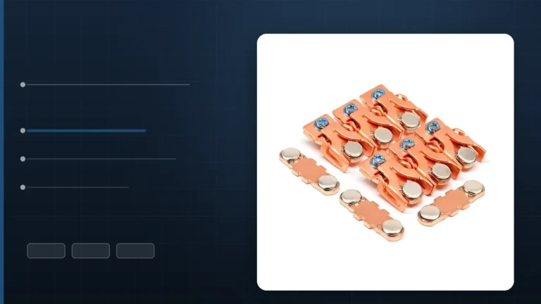
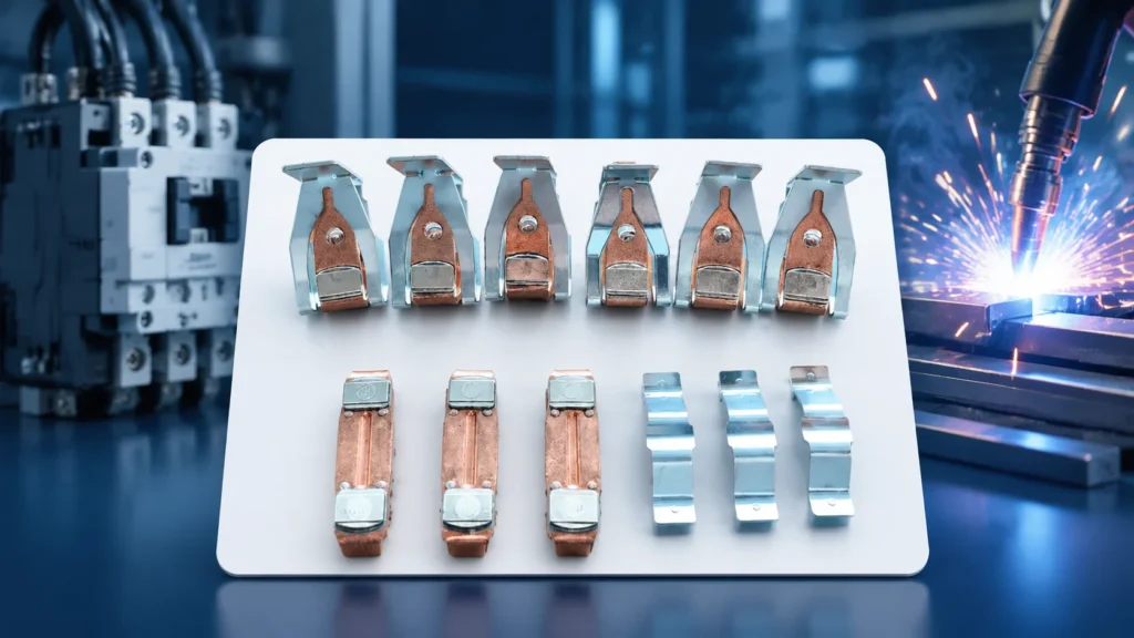
Contacts that have already lost their silver. A silver alloy tip erodes gradually, and the weld resistance of the contact rises as it thins. Once the alloy is gone the copper carrier is exposed, and copper welds far more readily than AgSnO2 or AgCdO. At that point the device is no longer protecting anything; it is a fuse that has forgotten how to blow. Contact thickness is the single most useful thing to measure during a contact wear inspection.
Sizing It: Thermal Current, Making Capacity and the Frame Ladder
The calculation has two independent legs, and both have to pass.
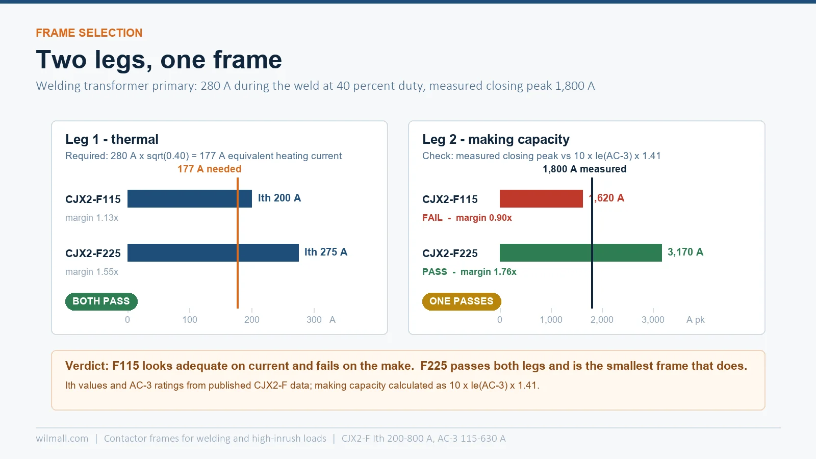
Leg one — thermal. Convert the welding duty into an equivalent RMS current. For a load that draws I during the weld and is off for the rest of the cycle at duty fraction D, the heating current is I × √D. Compare that with the frame’s rated heating current (Ith), not its AC-3 rating, and keep a margin for panel temperature.
Leg two — making. Take the peak current you actually measure on closing — with a current probe and a scope, because no multimeter will see it — and compare it with 10 × Ie(AC-3) × 1.41 for the candidate frame. If the measured peak is above that, the frame is wrong regardless of how comfortable the thermal result looked.
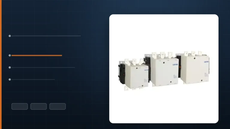
The table below uses published CJX2-F data, which makes the gap between the two legs visible. Note how far the AC-4 column sits below the AC-3 column on the same frame — that is the same physical device being asked to break a much harder current.
| Frame | Ith (A) | AC-3 380 V (A) | AC-4 380 V (A) | Making capacity, 10 × Ie × 1.41 (A peak) |
|---|---|---|---|---|
| CJX2-F115 | 200 | 115 | 52 | 1,620 |
| CJX2-F150 | 200 | 150 | 60 | 2,115 |
| CJX2-F185 | 275 | 185 | 79 | 2,610 |
| CJX2-F225 | 275 | 225 | 85 | 3,170 |
| CJX2-F400 | 450 | 400 | 138 | 5,640 |
| CJX2-F630 | 800 | 630 | 188 | 8,880 |
Worked example. A single-phase welding transformer on a 380 V supply draws 280 A during the weld at 40 percent duty. The equivalent heating current is 280 × √0.40 ≈ 177 A. On the thermal leg alone, a CJX2-F115 with Ith 200 A looks adequate — a 1.13 margin. Now measure the closing peak: the scope shows about 1,800 A, which is normal for a saturated core with a DC offset. F115’s making capacity is 1,620 A peak, so the frame fails the second leg by a clear margin. The next frame that passes both legs is the CJX2-F225, with Ith 275 A (a 1.55 margin on the thermal leg) and a making capacity of 3,170 A peak (a 1.76 margin on the making leg). That is a two-frame jump for a load that “only” needs 177 A, and it is the correct answer.
Why AC-3 Ratings Mislead on Welding Duty
The AC-3 rating is defined around a squirrel-cage motor: make at six times rated current at 0.35 lagging power factor, break at one times rated current. It is a making-heavy, breaking-light test, because a motor’s inrush collapses as it accelerates. Welding duty inverts that balance. The making current is large and repeated, and the breaking current — when the weld is interrupted under load — is not trivial either.
That is why a device chosen purely on AC-3 amps tends to fail on the make, and why the AC-3 versus AC-4 comparison is worth reading before specifying any high-inrush load. AC-4 breaks at six times rated current and is the closest published proxy for what a welding primary does to a contactor — which is also why the AC-4 column in the table above is roughly a third to a half of the AC-3 figure on the same frame. If you need a number to sanity-check a welding application, the AC-4 current is a much more honest starting point than AC-3.
Practical Fixes That Actually Work
- Go up one or two frames. This is the primary fix for a closing peak above the making capacity. The extra contact pressure, larger contact area and heavier springs all reduce both bounce and weld severity. The unit price increase is small against one unplanned line stop.
- Pre-charge capacitor loads. A resistor or pre-insertion contactor that charges the bank before the main contactor closes removes the short-circuit-like inrush entirely. For capacitor banks above a few tens of kvar this is standard practice, not an optional extra.
- Move very high cycle counts to solid state. If a welding machine closes thousands of times per shift, no electromechanical contactor will have a comfortable life. A thyristor or solid-state contactor switches at zero crossing and has no contacts to weld — at the cost of heat, leakage current and a failure mode that is short-circuit rather than open-circuit.
- Hold the coil voltage inside its window. Size the control transformer for the coil’s closing VA, not its sealed VA. On a CJX2-F225 the closing draw is around 1,200 VA against roughly 20 VA sealed — a factor of sixty. A control transformer sized on the sealed figure will sag on every pick-up, and the contactor will bounce its way into a weld.
- Use the right suppressor. RC or varistor on AC coils; reserve diode-only suppression for the smallest frames, or use diode-plus-zener where the manufacturer specifies it.
- Respect the 50 ms transition. Program it into star-delta timers and reversing logic rather than relying on contactor mechanics to provide it.
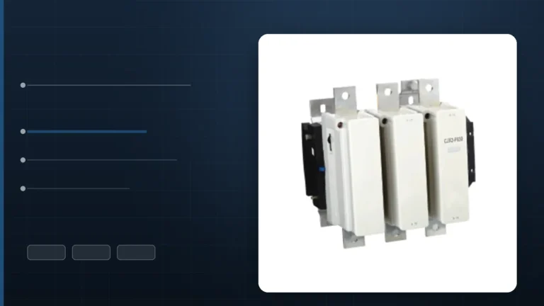
O CJX2-F series covers 115 A to 630 A in AC-3 with Ith ratings from 200 A to 800 A, which gives enough headroom to apply the two-leg calculation above without moving to a different product family.
Field Diagnosis: Inrush Weld or End-of-Life Weld?
Not every welded contactor is an application error. Before changing the specification, establish which failure you are looking at — the remedies are completely different.
| What you see | Most likely mechanism | What to do |
|---|---|---|
| Welded on a device with low operating hours and full contact thickness | Making weld — closing peak above making capacity | Measure the closing peak, go up a frame, add pre-charge if capacitive |
| Welded on a device near its rated electrical life, contacts visibly thin | Silver exhausted, copper carriers fused | Replace the contact kit or the device; review the maintenance interval |
| Random welds across several identical starters on one panel | Control voltage sag — undersized control transformer or long control runs | Measure voltage at the coil terminals during pick-up, resize the transformer |
| Welds appear after a suppressor was added or changed | Slow drop-out, possibly two-step drop-out | Remove diode-only suppression, fit RC or varistor |
| Welds concentrated after star-delta or reversing transitions | Transition time below 50 ms | Increase the timer setting, verify with a recorder |
| Contacts pitted and black but not welded | Arc erosion from normal breaking duty | Not a welding problem — see the wear guidance |
One diagnostic shortcut is worth remembering: a welded contactor that will not open is a safety event, not just a maintenance item. If the contactor feeds a motor that must stop on command, a welded device leaves the motor running with no way to disconnect it from the control side. That is why the stuck-closed condition deserves a written procedure rather than an improvised one — isolate upstream first, then investigate.
Conclusão
Contacts on welding and high-inrush loads weld because of what happens in the first three milliseconds, not because of what the load draws afterwards. Closing bounce restrikes the arc, an inrush above the making capacity blows the contacts apart while the coil still holds them, and a magnet system that releases too slowly cannot break the tack that results. Sizing on AC-3 amps hides all three.
The reliable method is two-legged: work out the equivalent heating current for the real duty, then check the measured closing peak against ten times the AC-3 rating times 1.41. When the second leg fails, go up a frame — or remove the inrush with a pre-charge circuit, or move to a solid-state device. If you are specifying a contactor for a welding machine, a capacitor bank or a transformer primary and want the frame selection checked against your measured switching current, send us the duty cycle and the scope trace and we will size it with you.
Perguntas frequentes
Why do contactor contacts weld shut on a welding machine?
Because the welding transformer presents a saturated core and a DC-offset first peak when it is switched on, so the closing current is several times the running current and arrives while the contacts are still bouncing. The arc energy at the contact spot melts the silver alloy, and the mechanism closes onto the molten pool. The running current is irrelevant to the failure.
Can I fix a welded contactor by tapping it?
A lightly tacked contactor sometimes releases if it is tapped or cycled a few times, but it should not be returned to service on that basis. The contact faces have been melted and re-solidified, the surface geometry is changed, and the weld resistance is now unpredictable. Replace the contact kit or the device, and fix the application cause before the new one fails the same way.
Is a bigger contactor always the answer for high-inrush loads?
For a closing peak above the making capacity, going up one or two frames is the standard and most reliable remedy. For capacitive loads, a pre-charge circuit removes the inrush instead of absorbing it and is usually cheaper than a two-frame jump at large ratings. For very high cycle counts, a solid-state contactor is the better answer than any electromechanical frame.
Does a surge suppressor cause contact welding?
It can, if it is the wrong type. A plain diode across an AC coil slows the magnet’s drop-out so much that the contacts separate slowly or briefly re-close during the break, and a light weld that would normally be broken by the contact springs is no longer broken. Use RC or varistor suppression on AC coils, and diode-plus-zener where the manufacturer requires it.
How do I measure the inrush that is welding my contacts?
With a current probe and an oscilloscope or a power quality analyser with a fast capture mode, triggered on the coil energisation. A clamp meter will not capture a peak that lasts a few milliseconds. Record the peak of the first half-cycle, not the RMS, because the peak is what the making capacity is compared against.
What is the minimum transition time for star-delta and reversing contactors?
About 50 milliseconds between star and delta, and between forward and reverse. Shorter transitions close into the motor’s residual voltage, which adds to the line voltage at an arbitrary phase angle and produces a peak that the contactor’s contacts may not survive.