IEC 60947-4-1 Explained: What the Standard Requires
Every number on a contactor nameplate comes from IEC 60947-4-1. Here is the clause-by-clause map - and the test report you should demand.
Read More
Battery storage, PV combiners, EV fast chargers and telecom power moved DC switching from a niche to a mainstream procurement question — and with it a crop of burned contactors in panels where someone selected an AC frame by amperage alone. DC is unforgiving: there is no current zero-crossing to extinguish the arc, so voltage rating, time constant and pole configuration decide everything. This page explains what actually changes at 600 V and 1000 V DC, and walks through a selection you can defend in a design review.
| Parâmetro | AC frame at 380/400 V | DC 600–1000 V requirement |
|---|---|---|
| Arc extinction | Current zero-crossing every 10 ms assists break | No zero crossing — arc must be stretched, cooled and split by design |
| Voltage rating per contact gap | Up to 690 V AC routinely | Typically 250–440 V per gap; higher voltage needs poles in series or a dedicated DC contactor |
| Time constant matters | Irrelevant (cosφ instead) | Decisive: DC-1 ≤1 ms, DC-3 ≤2 ms, DC-5 ≤7.5 ms at rated voltage |
| Pole configuration | 3-pole for three-phase load | 2–4 poles wired in series to multiply break voltage |
| Coil / control | AC coil from control transformer | DC coil with economy resistor or wide-range electronic coil |
| Failure mode if misapplied | Usually trips upstream protection | Sustained arc, contact destruction, fire risk in the panel |
The physics behind that first row — why DC arcs never self-extinguish and what manufacturers do about it — is covered in depth in why DC contactors need special arc extinction; the AC vs DC design split overall is in AC contactor vs DC contactor. This page stays on selection.
Nominal battery voltage is not the switching voltage. A “600 V” BESS string sits at 550–750 V depending on state of charge and equalization; a 1000 V PV string reaches 1100 V+ in cold conditions. Select the contactor’s DC rated operational voltage (Ue DC) against the maximum system voltage, not the nominal.
Then establish the load’s time constant L/R, because the same contactor that breaks 100 A DC-1 (resistive, ≤1 ms) may only break 25 A at DC-5 (motor or highly inductive, 7.5 ms). The IEC 60947-1 DC utilization categories quantify this:
| Category | Time constant | Typical load | Selection consequence |
|---|---|---|---|
| DC-1 | ≤1 ms | Resistive heating, electrolysis supplies | Full published DC rating usable |
| DC-3 | ≤2 ms | Shunt motors, starting/plugging | Derate vs DC-1; check plugging cycles |
| DC-5 | ≤7.5 ms | Series motors, hoists, traction | Heavy derating; dedicated DC contactor usually required |
Battery circuits deserve special respect: a battery is a low-impedance source with no natural current limitation, so the prospective fault current and the loop inductance (cable length adds L) both push toward the worst corner of the rating table.
| Aplicativo | Typical system voltage | Load character | Watch out for |
|---|---|---|---|
| PV string / combiner switching | 600–1500 V DC | Current-limited source, DC-1-like | Cold-weather Voc exceeds nominal; UV and altitude derating |
| BESS main disconnect | 400–800 V DC | Very high prospective fault current | Requires coordinated fuse/breaker; weld detection mandatory |
| EV DC fast-charger output | 200–1000 V DC | Controlled constant current | Frequent switching cycles; pre-charge sequence to limit inrush |
| Telecom -48 V DC plants | 48–60 V DC | High current, easy arc | Easy on voltage, brutal on current — check thermal rating |
| Traction / hoist DC drives | 250–750 V DC | DC-5 inductive | Severe derating; magnetic blow-out designs |
Most high-voltage DC ratings on multi-pole frames are achieved by wiring two, three or four poles in series so the breaking duty is shared: each gap sees a fraction of the arc voltage, and the arcs burn simultaneously in each chute. A frame rated 250 V per gap reaches ~500 V on two poles in series and ~1000 V on four. Rules that come with it:
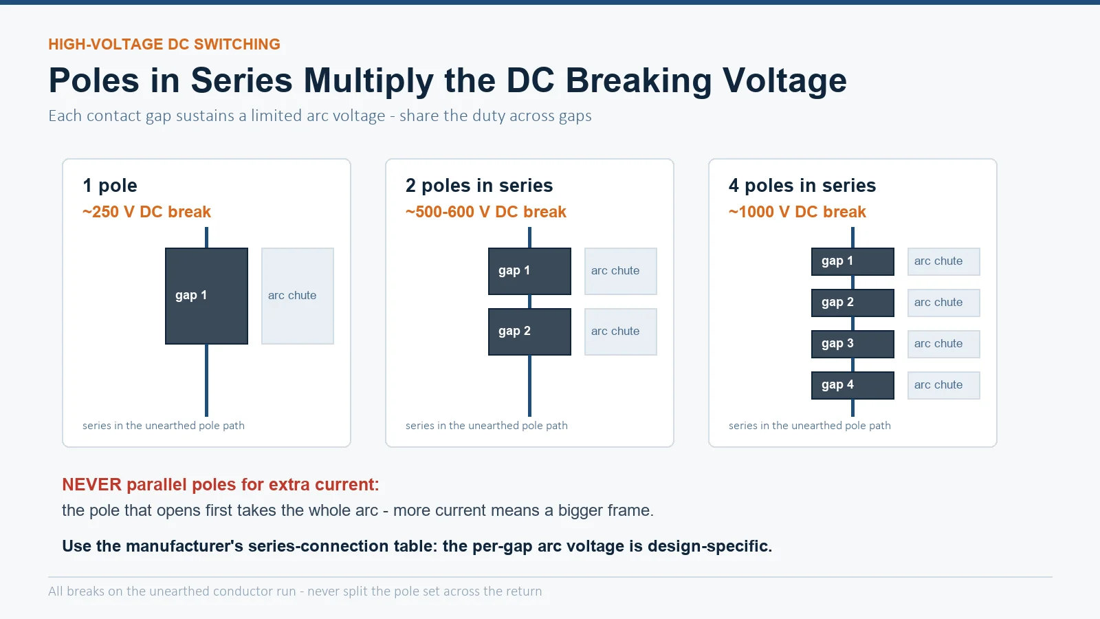
| Configuration | Approx. DC breaking voltage | Notes |
|---|---|---|
| 1 pole | ~250 V | Low-voltage DC, telecom plants |
| 2 poles in series | ~500–600 V | Common BESS and DC drive panel arrangement |
| 3 poles in series | ~750 V | Typical for 600 V-class systems with margin |
| 4 poles in series | ~1000 V | PV/EV fast-charge class; verify frame supports it |
Three deratings stack on top of the DC table, and they are the same ones that apply to AC selection but with sharper edges:
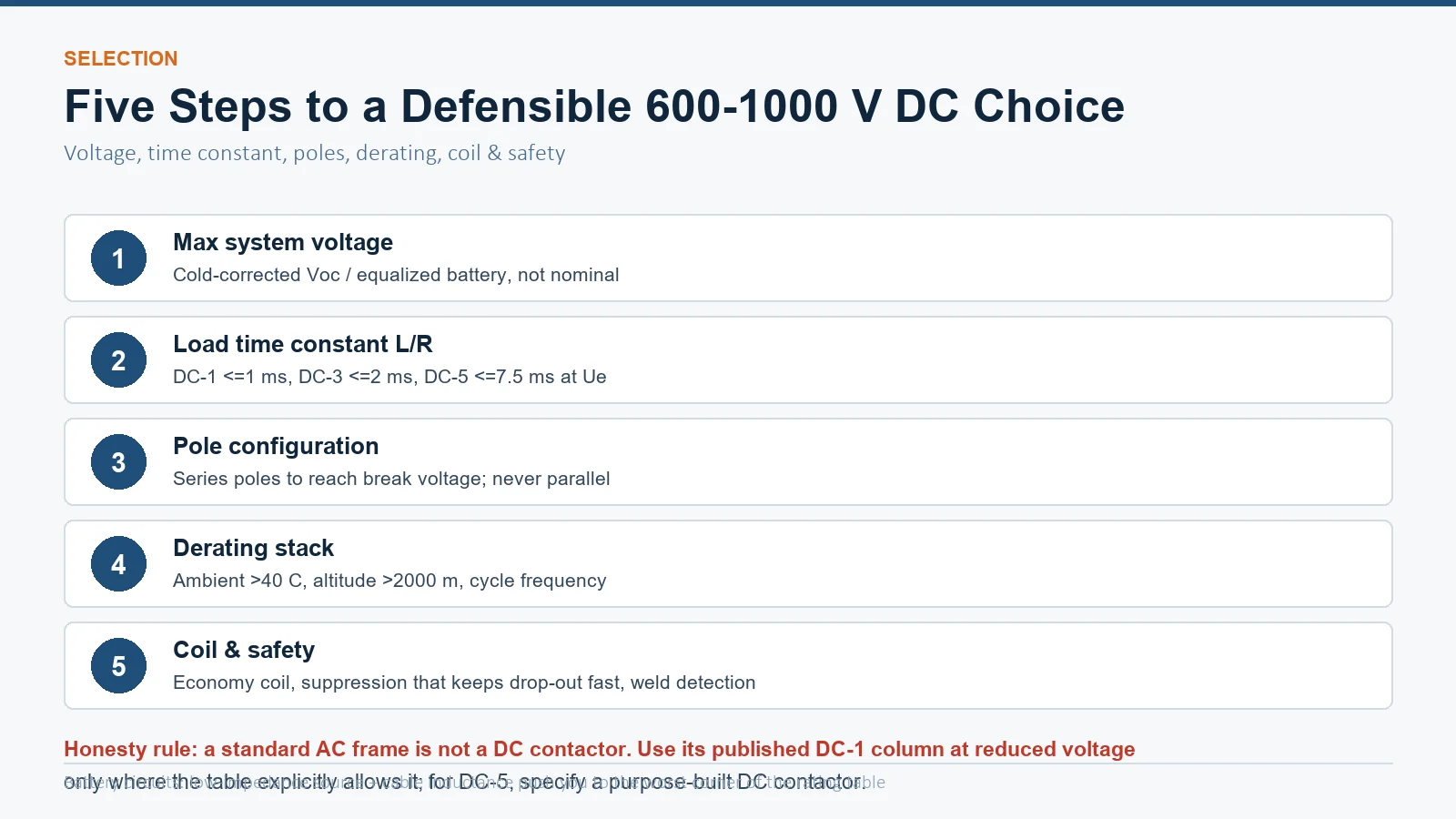
DC coils have no inrush problem (the inrush is set by resistance, not by a saturated core), but they hold significant power continuously — hence economy circuits and electronically controlled wide-range coils that drop holding power by 80–90 %. Two safety items belong in every high-voltage DC design:
And one honesty rule for procurement: a standard AC contactor is not a DC contactor. AC frames carry limited DC-1 ratings at reduced voltage, and using a 3-pole AC frame “because it is 690 V rated” at 600+ V DC is the exact misapplication that burns panels. Where the duty is genuinely DC-5, traction-class or purpose-built DC contactors with magnetic blow-out are the correct hardware.
Only within its published DC-1 rating at reduced voltage, and never by reading the AC voltage column. For 600–1000 V DC you need a DC-rated contactor or a multi-pole frame wired in series per the manufacturer’s DC table.
Each contact gap can only sustain a limited arc voltage. Wiring poles in series shares the breaking duty across several gaps and arc chutes, multiplying the breaking voltage without redesigning the contact system.
It is the load’s time constant. DC-1 (≤1 ms) is near-resistive and uses the full rating; DC-3 (≤2 ms) and DC-5 (≤7.5 ms) store inductive energy, stretch the arc, and force progressively lower break currents at the same voltage.
Take the maximum open-circuit voltage (cold temperature corrected), the string current, confirm the DC-1-ish character of the load, then select a frame whose series-connected DC rating exceeds that voltage with margin — and verify altitude derating for mountain sites.
Poles never open or close simultaneously, so the first pole to break carries the entire arc duty, and during closing the current divides unequally by contact resistance. For more current, use a larger frame.
No — a DC coil holds the armature with constant force and is silent. If a nominally DC-operated contactor buzzes, its rectifier or economy module has failed and it is effectively running on AC through the wrong circuit.
Specifying switching for a battery, PV or charging system? Start from the CJX2-F series AC contactors for panel control duties and low-voltage DC applications, and send us your system voltage, load time constant and switching frequency — our engineers will confirm which duty the frame can legitimately carry and where a dedicated DC contactor is the honest answer, within one working day.