Índice
When you’re working with automation, robotics, or industrial control systems, you’ll often come across the term “encoder.”
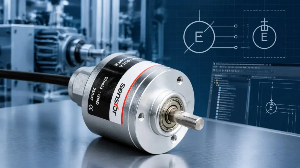
Quick answer: the encoder symbol is a circle with an E inside and a shaft stub – incremental types add A, B and Z output terminals, absolute types add a clock and data pair (SSI, BiSS). The body symbol is identical for both; the terminals and the signal wires are what differ.
But have you ever stopped to wonder what the encoder symbols means in technical diagrams?
Let’s break it down together—so the next time you see an encoder symbol, you’ll know exactly what you’re looking at and why it matters.
What Is an Encoder Symbol?
An encoder symbol is a standardized graphic used in electrical and automation schematics to represent an encoder component.
Just like a musical note tells a musician what to play, the encoder symbol tells engineers and technicians what’s happening in the circuit.
It’s a visual shorthand that helps everyone speak the same technical language, no matter where they’re from.
International Standards for Encoder Symbols
You might think every company draws these symbols their own way, but that would be chaos. T
hat’s why organizations like the International Electrotechnical Commission (IEC) created standards—specifically IEC 60617—to make sure encoder symbols look and mean the same thing everywhere.
In the United States, you’ll also see standards from ANSI and IEEE, but IEC 60617 is the global go-to.
According to these standards, an encoder symbol usually appears as a rectangle (representing the device) with input and output terminals.
For rotary encoders, you’ll often see a small circle or arc attached, showing the rotating shaft.
Sometimes, the symbol includes arrows for direction or labels like “ENCODER” to make things crystal clear.
Common Forms of Encoder Symbols
Not all encoders are created equal, and neither are their symbols. Here’s what you’ll typically find:
- Rotary Encoder Symbol: A rectangle with a protruding circle or arc, sometimes with an arrow indicating rotation.
- Linear Encoder Symbol: A rectangle with parallel lines or a straight arrow, representing linear movement.
- Digital Encoder Symbol: For logic circuits, you might see a triangle or rectangle with multiple inputs and fewer outputs, labeled with the number of lines (like “8-to-3”).
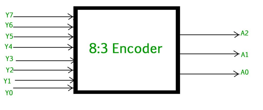
You’ll also spot variations for incremental and absolute encoders. Incremental encoder symbols may include extra lines for reference (like the Z-channel), while absolute encoders might feature additional labels or a unique outline.
How to Read and Draw Encoder Symbols
When you see an encoder symbol on a schematic, pay attention to:
- Inputs and Outputs: These show how the encoder connects to the rest of the system.
- Labels: Words like “ENCODER,” “ABS,” or “INC” help you spot the type.
- Arrows or Circles: Indicate movement direction or rotation.
If you’re drawing your own diagrams, stick to the standards. Use clear rectangles, mark all terminals, and add any necessary labels. This keeps your documentation clear and professional.
Encoder Symbol in Practical Applications
Let’s get practical. Imagine you’re reading a control panel diagram for a conveyor system. You’ll see the encoder symbol right next to the motor, with output lines leading to a PLC. In a robot arm schematic, the encoder symbol sits at each joint, showing how the system tracks position and movement.
Case in point: If you’re troubleshooting why a conveyor isn’t stopping where it should, tracing the encoder symbols in the wiring diagram helps you quickly find the right connections and signals.
Encoder Symbol and Related Circuit Symbols
Encoders aren’t the only devices with special symbols.
You’ll also run into decoders, sensors, and transducers. While they might look similar—a rectangle here, a triangle there—each has its own unique features.
For example, a decoder symbol usually has more outputs than inputs, while a sensor symbols might include a wave or arrow. Always double-check the labels and context to avoid confusion.
Quick answer: the encoder symbol is a circle with an E inside and a shaft stub – incremental types add A, B and Z output terminals, absolute types add a clock and data pair (SSI, BiSS). The body symbol is identical for both; the terminals and the signal wires are what differ.
The Rotary Encoder Symbol With Its Terminal Set
On schematics the encoder appears as device B1 (IEC 81346 letter code B for transducers) – a circle, an E, and one terminal line per signal. A differential incremental encoder has the fullest terminal set, and each pair has a defined meaning:
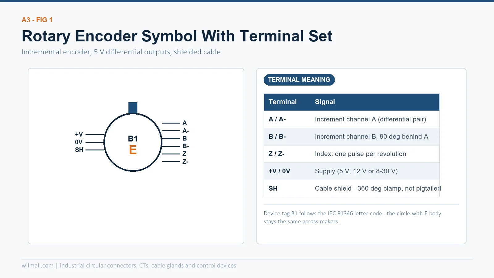
| Terminal | Signal | Wiring note |
|---|---|---|
| A / A- | Increment channel A (differential pair) | Twisted pair, keep away from motor cables |
| B / B- | Channel B, 90 degrees behind A | Direction sensing comes from this lag |
| Z / Z- | Index, one pulse per revolution | Use for homing and speed verification |
| +V / 0V | Supply: 5 V, 12 V or 8-30 V depending on model | Check the driver input before ordering |
| SH | Cable shield | 360-degree clamp at the drive end, never pigtailed |
The same body symbol appears on our GOS38D incremental encoder product page with the matching terminal table, so the drawing and the datasheet can be checked side by side.
Incremental vs Absolute: Same Circle, Different Wires
Both variants draw as a circle with an E. What changes is the interface: incremental outputs A, B and Z as pulse trains; absolute outputs a coded position over SSI, BiSS or an analog signal. That difference decides restart behaviour after a power cut, and it is the first thing to check when an existing drawing is reused on a new machine.
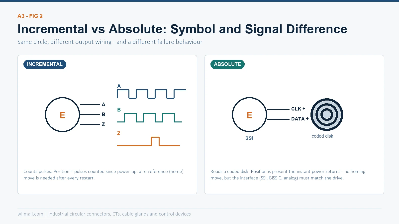
| Incremental | Absolute | |
|---|---|---|
| Symbol terminals | A, B, Z (+ supply) | CLK, DATA (+ supply) |
| Position after power-up | Counts from zero – homing move needed | Real position immediately |
| Interface to match | TTL, HTL, push-pull, line driver | SSI, BiSS C, 0-10 V, 4-20 mA |
| Uso típico | Speed and length measurement | Position loops, multi-turn axes |
If the choice between the two is still open, our absolute vs incremental selection guide walks through resolution, speed and environment, and the encoder vs potentiometer comparison covers the cheaper alternative that the symbol is often confused with.
Drawing the Symbol in EPLAN and CAD Libraries
EPLAN ships a generic transducer symbol that satisfies IEC 60617, but most panel builders rename it and re-pin it to match the encoder terminal table above – that way the PLC card assignment in the software matches the physical terminal numbers. Two habits prevent the usual field calls: keep differential pairs on adjacent pins in the macro, and give the shield its own connection point so it survives symbol rotation. On the drawing the designation stays B1, B2 and so on; the circle-with-E body never changes between manufacturers, which is exactly why the terminal table – not the symbol – carries the ordering information.
Conclusão
Understanding the encoder symbols isn’t just about reading diagrams—it’s about speaking the universal language of engineering.
Whether you’re designing a new system, troubleshooting an old one, or just trying to make sense of a complex schematic, knowing what the encoder symbol means will save you time and headaches.
So next time you spot that little rectangle with a circle or arrow, you’ll know: that’s the heartbeat of precision motion in your automation system.
Perguntas frequentes
Why do we use standardized encoder symbols?
Standard symbols keep diagrams clear and consistent, making global collaboration possible.
Where can I find the official encoder symbol?
Check IEC 60617 or your industry’s preferred standards for the latest symbol definitions.
How can I tell if a symbol is for an incremental or absolute encoder?
Look for labels or extra lines—incremental encoders may show reference channels, while absolute encoders might have unique markings.