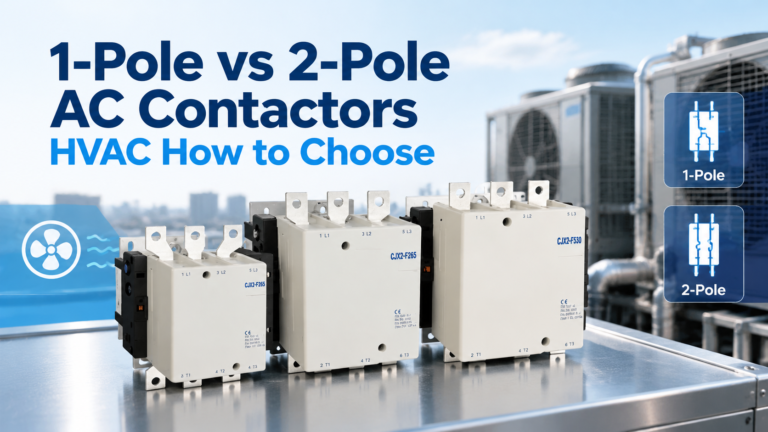
1-Pole vs 2-Pole AC Contactors (HVAC): How to Choose
Pole count is decided by the wiring system, not the frame size. Compare 1-pole and 2-pole HVAC contactors, the bypass-bar construction and the safe replacement rules.
Read More
A standard AC contactor is a single-answer device: energise the coil, the contacts close; de-energise it, they open. That single behaviour covers most motor control. It does not cover three common situations where the switching task itself is different — holding a state without power, running a motor in two directions, and interrupting current at medium voltage without an arc chute. Those three jobs are handled by latching contactors, reversing contactors, and vacuum contactors.
This guide explains what each of the three families actually is, how its internal mechanism differs from a standard contactor, which applications justify the extra cost, and — more useful for anyone specifying equipment — where each one will get you into trouble. The last point matters most, because two of the three families have failure modes that a standard contactor simply does not have.
If you only need the short version, the table below is the whole article in six rows. The sections that follow explain the engineering behind each row.
| Family | What is different | What it solves | Typical application | Where it fails you |
|---|---|---|---|---|
| Standard contactor | Spring-return, coil must stay energised | Simple on/off switching | DOL motor starting, heaters, lighting | Drops out on power loss (usually what you want) |
| Latching contactor | Bistable mechanism holds the last state with no coil current | State memory with zero holding energy | Load shedding, lighting groups, remote switching | Does not drop out on power loss — unusable for safety stop functions |
| Reversing contactor | Two contactors, mechanically and electrically interlocked | Forward/reverse rotation of a three-phase motor | Hoists, conveyors, door operators, valve actuators | Cannot protect against a welded contactor being reversed into |
| Vacuum contactor | Contacts sealed in a vacuum bottle instead of an air arc chute | Frequent or high-energy interruption with almost no contact erosion | MV motor control 1.14–12 kV, mining, heavy-duty LV | Current chopping overvoltages; no visible isolation gap |
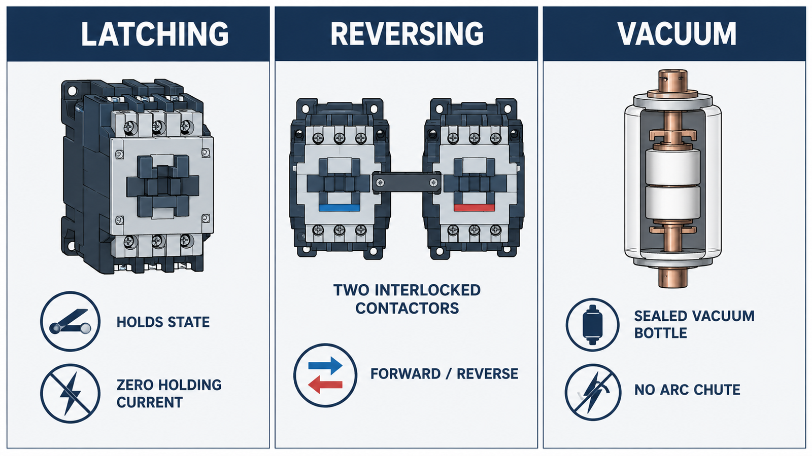
A latching contactor — also sold as a bistable, impulse, or magnetic latching contactor — changes state when it receives a short pulse and then stays in that state after the pulse ends. There is no continuous coil current in either position. This is the defining property, and everything else about the device follows from it.
Permanent-magnet latching uses a magnet in the magnetic circuit to hold the armature in the closed position. A short energising pulse of one polarity drives it closed; a pulse of the opposite polarity, or a pulse to a separate reset coil, drives it open. The magnet does the holding, so the coil is only ever energised for the duration of the pulse.
Mechanical latching uses a spring-loaded latch that engages when the armature closes. A small trip coil releases the latch. The holding force comes from a mechanical detent rather than a magnet, which makes the release action more definite but adds wear parts.
Both types share the same coil constraint: the coil is short-time rated. It is designed for a pulse of roughly 0.1 to 0.3 seconds, not for continuous energisation. Wiring a latching contactor coil to a maintained contact will overheat and destroy it, and this is one of the most common installation errors on these devices.
The commercial case for latching is holding loss. A large frame contactor coil draws on the order of 10 to 25 W while holding. Take a mid-range value of 15 W on continuous duty:
On top of the energy saving, a latching contactor produces no continuous hum, generates no coil heat inside the enclosure, and does not contribute to panel temperature rise — which in a densely packed cabinet can matter more than the electricity cost, because every watt of coil loss is a watt the panel cooling has to remove.
A latching contactor does not open when control power is lost. It holds its last commanded state. That is the entire point, and it is also why a latching contactor must never be used as the switching element in a stop circuit, an emergency stop circuit, or any function where the required behaviour on power failure is “de-energise and stop”.
Permitted uses follow directly: memory functions after a supply interruption, remote switching where re-energising everything on restoration would be undesirable or dangerous, load-shedding schemes where a non-critical group must stay off until deliberately re-enabled, and lighting circuits where a power dip should not black out a space. Forbidden uses: motor start/stop control, safety-related stopping, and any circuit covered by a risk assessment that assumes de-energisation on failure.
There is a second, subtler failure mode. If the latch mechanism wears or the permanent magnet weakens, the contactor may fail to release. Because there is no spring-return, nothing forces it open. Maintenance schedules for latching contactors should therefore include a periodic release test, not just a contact inspection — a test that is easy to forget because the device appears to be working correctly every time it is checked in the closed state.
A reversing contactor assembly is two standard contactors mounted together with a mechanical interlock between their armatures, plus cross-wired normally-closed auxiliary contacts for electrical interlock. Reversing a three-phase motor is done by swapping any two of the three supply phases, and the second contactor does exactly that: its line and load terminals are wired in reverse order relative to the first.
Nothing about the contactor itself is special. What makes the assembly safe is the interlock, and what makes it work is the dead time.
O mechanical interlock is a physical linkage that blocks one armature from moving while the other is closed. It works even if the control circuit is miswired or a relay contact welds, because it does not depend on any electrical signal. IEC 60947-4-1 and NEMA ICS 2 both treat a mechanical interlock as mandatory on reversing assemblies.
O electrical interlock is a normally-closed auxiliary contact from each contactor wired into the other’s coil circuit. It acts first, before the mechanical interlock is needed, and it also prevents the control circuit from holding both coils energised simultaneously. It is a second layer, not a substitute: an auxiliary contact can fail, and control wiring can be modified in the field.
When the forward contactor opens, an arc persists for a few milliseconds while the arc chute cools and de-ionises the gap. If the reverse contactor closes before that arc is extinguished, the two arcs overlap and you have a phase-to-phase short circuit at the contact tips. The result is a flashover inside the contactor, often destroying both devices and occasionally the enclosure.
Field practice is a minimum changeover dead time of 50 to 100 ms, and longer for large frames with heavy armatures and long arc durations. In practice this is implemented with an off-delay timer in the control circuit, or with a PLC/soft-starter that sequences the two outputs. Setting the delay to zero because the machine “responds faster” is a common and expensive mistake.
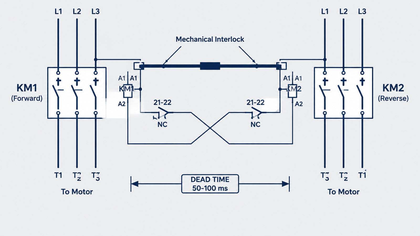
Here is the gap that most reversing-contactor documentation does not address. Suppose the forward contactor’s contacts weld shut while running. The operator commands reverse. The forward contactor is already closed — mechanically, permanently — so the interlock correctly blocks the reverse contactor from closing. The machine does not reverse. That is the good outcome.
But if the operator then opens the upstream isolator and closes it again, or if the control circuit is reset in a way that momentarily drops the reverse coil and re-energises it after the forward armature has been forced back by the interlock spring, the interlock may no longer be blocking. The reliable protection against reversing into a welded contactor is not the interlock at all — it is weld detection: monitoring the forward contactor’s auxiliary contacts, or the motor current, and refusing to accept a reverse command until the forward circuit is confirmed open. On hoists and other gravity-loaded applications, this is worth the extra relay.
Each contactor in a reversing pair carries the full motor current, so each is sized for the full AC-3 rating — not half. The utilisation category matters more than usual here, because reversing duty frequently involves plugging (reversing while the motor is still turning), which pushes the duty toward AC-4. AC-4 duty can require a contactor two or three frame sizes larger than the AC-3 rating for the same motor. If the application reverses a loaded conveyor or a hoist under load, size on AC-4 and accept the larger frame.
A vacuum contactor interrupts current inside a sealed vacuum interrupter — a ceramic or glass envelope evacuated to roughly 10⁻⁴ Pa, containing a fixed contact and a moving contact made from copper-chromium (CuCr) alloy. There is no arc chute, no splitter plates, and no ionised air to manage. The arc burns in metal vapour from the contacts themselves, and it is extinguished within a few milliseconds when the current passes through zero and the vapour condenses back onto the contact surfaces.
That single design change produces the properties vacuum contactors are bought for: very long electrical life, silent operation, a sealed switching chamber that is immune to dust and humidity, and a much smaller footprint than an equivalent air-break device at medium voltage.
| Voltage class | Uso típico | Why vacuum |
|---|---|---|
| 1.14 kV | Mining, tunnelling, heavy mobile plant | Sealed chamber tolerates dust, moisture and frequent switching |
| 3.6 kV / 7.2 kV | MV motor control centres, pump and fan drives | High operation counts without contact replacement |
| 12 kV | Utility and industrial MV distribution, capacitor switching | Compact, maintenance-free interruption at high energy |
| LV heavy duty | Steel, welding, high-cycle automation | Long mechanical and electrical life in a small frame |
Current chopping overvoltage. A vacuum arc does not wait politely for a natural current zero in the way an air arc does. At small inductive currents — typically below a few tens of amps, as happens when a motor is starting or running lightly loaded — the arc can be chopped abruptly before the natural zero crossing. The stored magnetic energy in the motor winding then has nowhere to go and appears as a steep-fronted voltage transient at the motor terminals. Repeated chopping events stress winding insulation, and on old motors with degraded insulation this is a recognised cause of failure.
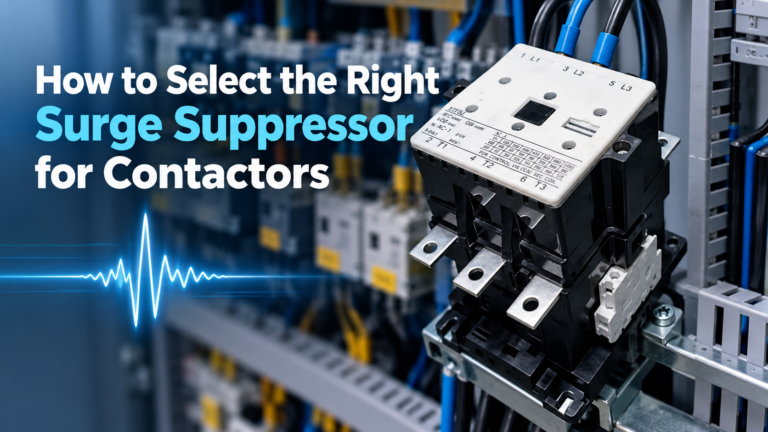
The mitigation is a surge suppressor on the load side of the contactor — an RC network or a metal-oxide varistor, sized for the motor’s inductance and the system voltage. Specifying a vacuum contactor for motor duty without a load-side suppressor is an incomplete specification, and it is the most common omission in vacuum contactor projects.
No visible isolation gap. The contacts are sealed inside an opaque bottle. You cannot see whether the contactor is open, and you cannot verify it by inspection. Safe isolation therefore requires a separate visible isolating device — a disconnect switch or a withdrawable truck — upstream of the vacuum contactor. Standards and site safety rules generally require this, and it is a design decision that has to be made at the panel layout stage, not afterwards.
A third, smaller cost: vacuum integrity cannot be checked visually. A bottle that has lost vacuum may still operate for a while and then fail to interrupt. Periodic withstand-voltage testing is the only reliable check, and it needs to be on the maintenance schedule from day one.
| Criterion | Latching | Reversing | Vacuum |
|---|---|---|---|
| Holding current | Zero | Continuous (both coils rated continuous) | Continuous |
| Behaviour on power loss | Holds last state | Opens (standard contactor behaviour) | Opens |
| Switching element | One contactor, bistable mechanism | Two interlocked contactors | Vacuum interrupter bottle |
| Arc management | Conventional arc chute | Conventional arc chute | Metal-vapour arc in vacuum |
| Electrical life at rated current | Standard | Standard, reduced by plugging duty | 10–100× standard |
| Panel space | Same as standard | Roughly double | Compact for the voltage class |
| Dominant cost driver | Latch mechanism and short-time coil | Second contactor plus interlock kit | Vacuum bottle and mechanism |
| Maintenance focus | Release test, latch wear | Interlock adjustment, dead time, weld check | Vacuum integrity, load-side suppressor |
| Aplicativo | Correct choice | Motivo |
|---|---|---|
| Lighting groups that must resume after a power dip | Latching | State memory with no holding energy |
| Non-critical load shedding | Latching | Stays off until deliberately re-enabled |
| Conveyor forward/reverse | Reversing, sized on AC-4 | Plugging duty, dead time required |
| Crane hoist up/down | Reversing plus weld detection | Gravity load, welded contact risk |
| MV pump motor, frequent starts | Vacuum plus load-side suppressor | High operation count, chopping overvoltage |
| Dusty or humid plant room | Vacuum | Sealed chamber, no arc chute contamination |
| Emergency stop circuit | Standard contactor or safety contactor | Must de-energise on failure — latching is disqualified |
| Simple DOL motor starter | Standard contactor | No benefit from the other three families |
For the underlying on/off behaviour that all four families share, see what a contactor is and how it works. For the motor-starting context that determines the utilisation category, see contactor selection for motor starters.
| Mistake | What goes wrong | Correction |
|---|---|---|
| Energising a latching coil continuously | Short-time coil overheats and fails within minutes | Pulse only, 0.1–0.3 s, from a momentary contact |
| Using a latching contactor in a stop circuit | Machine does not stop on power loss | Use a standard or safety contactor for stop functions |
| Setting reversing dead time to zero | Overlapping arcs, phase-to-phase flashover | 50–100 ms minimum, longer for large frames |
| Sizing one reversing contactor on half the motor current | Overheating and welded contacts on that side | Each contactor sized for full AC-3 or AC-4 current |
| Vacuum contactor without a load-side suppressor | Chopping overvoltages damage motor insulation | Add RC or MOV suppressor at the motor terminals |
| Relying on a vacuum bottle for visible isolation | No verifiable isolation gap for maintenance | Provide an upstream visible isolating device |
If a latching or reversing contactor is already installed and behaving oddly — failing to release, chattering, or refusing to reverse — the diagnostic sequence in contactor troubleshooting applies to the mechanism as well as the coil. For the arc physics that explains why vacuum interruption behaves so differently from air-break interruption, see why DC contactors need special arc extinction.
Whichever family you specify, the purchasing document should pin down more than the current rating. For latching contactors: coil pulse voltage and permitted pulse duration, whether the reset is by reverse polarity or a separate coil, and the required release test interval. For reversing assemblies: the interlock type (mechanical, electrical, or both), the required dead time, and whether weld detection is included. For vacuum contactors: the interrupter voltage class, the required load-side suppression, the upstream visible isolating device, and the vacuum integrity test interval.
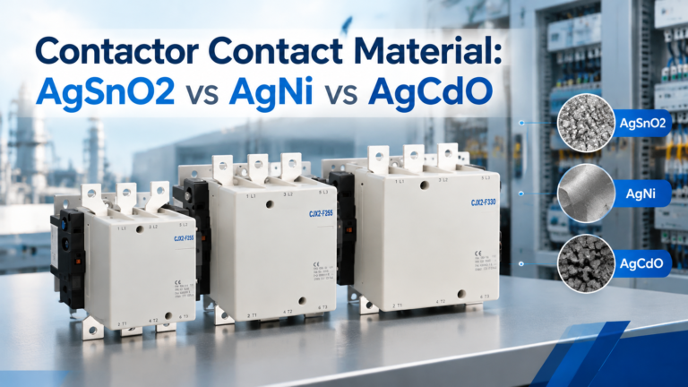
Getting those five lines onto the datasheet prevents most of the field problems described above, because each one corresponds to a decision that is cheap at the design stage and expensive afterwards. For standard frames in the CJX2-F range that cover the reversing and heavy-duty cases discussed here, the CJX2-F series AC contactors page lists the available ratings and configurations.
Technically it can switch motor current, but it should not be used as the start/stop element. Because it holds its last state, a control power failure leaves the motor either running or stopped with no defined behaviour, and there is no spring-return to guarantee opening. Use a standard contactor with a maintained or momentary control circuit instead.
Typically 0.1 to 0.3 seconds, per the manufacturer’s datasheet. The pulse must be long enough for the armature to complete its travel and for the latch or magnet to engage, and short enough to stay inside the coil’s short-time rating. A pulse that is too short leaves the contactor in an indeterminate half-closed state, which is worse than not switching at all.
The most likely cause is insufficient dead time: the reverse contactor is closing while the forward arc is still conducting, producing a phase-to-phase short. Check the off-delay setting first. If the delay is correct, check whether the forward contactor has welded contacts, and whether the mechanical interlock is correctly adjusted and not bypassed.
For motor loads, yes. Current chopping in a vacuum interrupter can produce steep-fronted overvoltages at the motor terminals, and a load-side RC or MOV suppressor limits them. For resistive loads the risk is much lower, but many specifications still call for suppression as standard practice on the load side.
For a two-pole load, a three-pole contactor can be used with one pole left unused, and this is common as an emergency substitution. The reverse — using a 2-pole device where three phases must be switched — is never acceptable, because one phase remains unswitched and the motor runs single-phased.
They are usually the same device described two ways. “Latching” and “mechanically held” both mean the contactor maintains its position without continuous coil current. The distinction, where a supplier makes one, is between permanent-magnet holding and a mechanical detent; both are bistable and both hold state on power loss.
These three families are not upgrades to a standard contactor. Each one solves a specific problem — state memory, direction reversal, or high-energy interruption — and each one introduces a failure mode that a standard contactor does not have. Latching removes holding current but also removes fail-safe drop-out. Reversing adds direction control but cannot defend against a welded contactor. Vacuum adds switching life but needs load-side suppression and a separate isolation point.
Specify on the problem, not on the feature list: identify what the circuit must do on power loss, how often it switches, and what the isolation requirement is. Those three answers pick the family. The rest is sizing.