


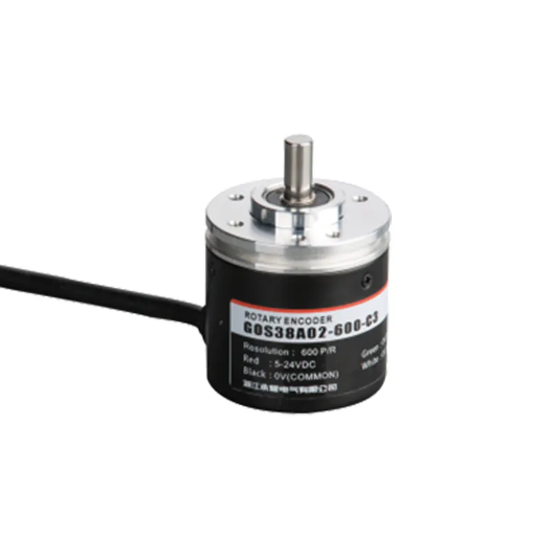
GOS38A02 Codificador rotativo incremental com eixo semi-oco e IP65
O codificador rotativo incremental GOS38A02 foi projetado para o controle preciso de movimentos em aplicações de automação industrial. Com um diâmetro compacto de 38 mm e eixo semi-oco, ele fornece feedback preciso de posição e velocidade com resoluções de até 10.000 pulsos por revolução.
Interested in this product?
Please contact our sales team for the latest pricing, lead time, and technical consultation.
O codificador rotativo incremental GOS38A02 foi projetado para o controle preciso de movimentos em aplicações de automação industrial. Com um diâmetro compacto de 38 mm e eixo semi-oco, ele fornece feedback preciso de posição e velocidade com resoluções de até 10.000 pulsos por revolução. Sua construção robusta com classificação IP65 garante um desempenho confiável em ambientes adversos. Compatível com vários PLCs e sistemas de controle, o GOS38A02 oferece sinais de saída versáteis, incluindo coletor aberto, push-pull e driver de linha, garantindo uma integração perfeita em máquinas de transporte, robótica, CNC e de embalagem.
Principais recursos
Codificador rotativo óptico incremental com opções de alta resolução de 100 a 10.000 PPR
Projeto de eixo semi-oco (normalmente 8 mm de diâmetro) para instalação direta do motor e fácil acoplamento
O invólucro com classificação IP65 protege contra a entrada de poeira e água, proporcionando durabilidade industrial
Ampla faixa de tensão de entrada CC de 5 a 24V para compatibilidade flexível do sistema
Vários tipos de sinal de saída: coletor aberto (NPN), push-pull complementar e sinais diferenciais do driver de linha de 5V
Circuito anti-interferência para saída de sinal estável e resistente a ruídos
Diâmetro externo compacto de 38 mm, facilitando a integração em montagens mecânicas apertadas
Opções de cabos longos com luvas de proteção de borracha disponíveis
Vantagens do produto
Medição de alta resolução que permite o controle preciso da velocidade e da posição
O eixo semi-oco facilita a instalação e o alinhamento do eixo
A robusta proteção IP65 aumenta a longevidade do codificador em ambientes difíceis
As saídas versáteis suportam uma ampla gama de aplicações de controle industrial
A imunidade aprimorada a ruídos de sinal garante feedback consistente em ambientes com ruídos elétricos
Tamanho compacto que economiza espaço, adequado para aplicações com espaço de instalação limitado
Modelo e significado do produto
| G | 0 | S | 38 | □ | A | 02 | 2000 | C | 3 | 2M | |||
| Categoria de produto | Tipo de produto | Forma de eixo principal | Contorno de produto | Tamanho do eixo principal, furo do eixo | Saída e formulário de selagem | Esboço estrutura | Resolução | Formulário de saída | Sinal de saída | Cabo | |||
| G:incremental tipo | 0:megneto- eletricidade | S: eixo sólido | 38:φ38mm | □:φ6mm | A: saída lateral de borracha | 02:2esboço estrutura2 | 10,20,50,60, 100,200,360, 400,500,600, 800,1000, 1024,1200, 2000,2048, 2500,3000, 3600,5000 | C: saída de coletor aberto F: saída complementar T:saída push pull L:Saída de acionamento de 5V A:Saída de acionamento de 24V | 1:fase Asignal 2:sinal de fase AB 3:fase do sinal ABZ 4:fase Sinal ABA/B/ 5:fase do sinal ABZA/B/Z/ | Padrão 2m linha, para não 2m, A rotulagem é suficiente |
Tabela de fiação
| Cor da linha | Sinal de saída C/F | – | Cor da linha | Sinal de saída |
| marrom | VCC | marrom | VCC | |
| azul | GND | |||
| azul | GND | |||
| preto | Uma fase | |||
| preto | Uma fase | branco | Fase B | |
| laranja | Fase Z | |||
| branco | Fase B | |||
| preto vermelho | Fase | |||
| laranja | Fase Z | branco vermelho | Fase B | |
| vermelho alaranjado | Fase Z | |||
| escudo | F -G | |||
| escudo | F -G |
Diferença de fase de saída
saída complementar/coletor NPN saída de circuito aberto/saída push pull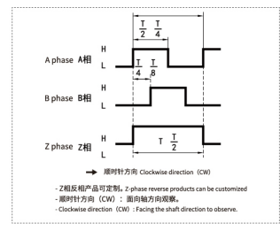
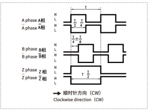
saída de acionamento de linha longa
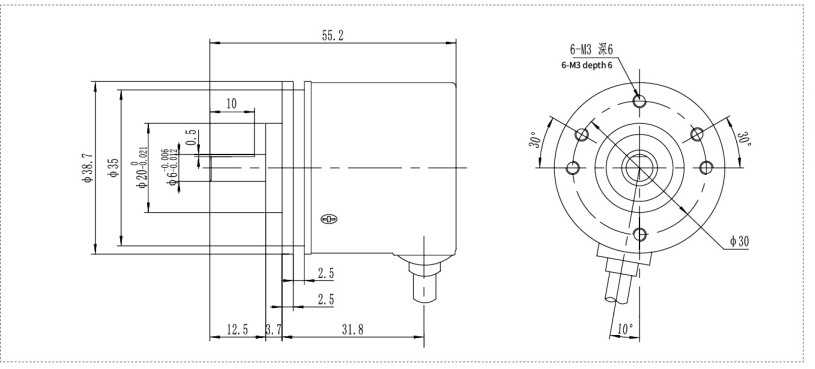
Desenhos mecânicos (mm)
Cenários de aplicativos
Medição de velocidade e posição de motores industriais para automação
Máquinas CNC para posicionamento preciso de ferramentas e feedback de rotação
Controle de velocidade e posição da correia transportadora em linhas de embalagem
Robótica que requer feedback preciso de juntas e eixos
Máquinas de impressão para sincronizar os movimentos do rolo e da folha
Linhas de montagem automatizadas que exigem feedback rotativo de alta confiabilidade
Instalação e manutenção
Verifique o diâmetro do eixo e combine-o com o eixo do codificador semi-oco de 8 mm para obter um encaixe seguro.
Alinhe os eixos cuidadosamente para evitar estresse mecânico e garantir um feedback preciso. Recomenda-se o uso de acoplamento flexível.
Fixe o codificador firmemente com parafusos de montagem para evitar vibrações ou movimentos de rotação.
Conecte a fonte de alimentação entre 5 e 24 VCC e conecte os sinais de saída de acordo com a interface necessária (consulte os diagramas de fiação).
Use cabos de par trançado blindados sempre que possível para minimizar a interferência eletromagnética.
Mantenha o compartimento do codificador limpo e livre de acúmulo de poeira.
Inspecione periodicamente as conexões elétricas quanto a aperto e sinais de desgaste.
Substitua o codificador imediatamente se a integridade do sinal se degradar ou se ocorrerem danos mecânicos.