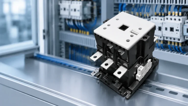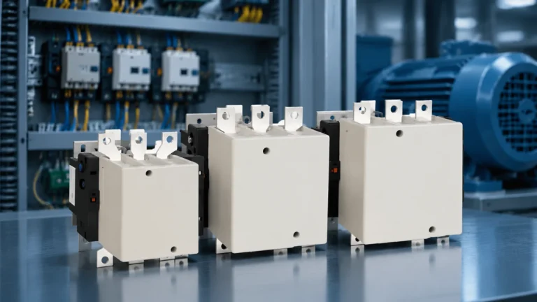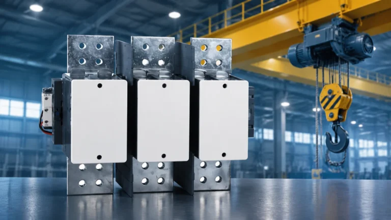
Quick answer: An electrically held lighting contactor needs continuous coil voltage to keep its contacts closed — it drops out the moment control power is lost, consumes a few VA per pole set forever, and hums. A mechanically latched lighting contactor uses a momentary pulse (typically 0.1–0.3 s) to a latch coil and a second pulse to an unlatch coil; once set, a mechanical latch holds the contacts with zero holding power and no noise, and the lights stay on through a power dip. Choose electrically held for fail-safe, simple two-wire control; choose mechanically latched for large banks held on for long hours, for BMS or time-clock control, and wherever a voltage blip must not black out a hall of HID lamps that then needs ten minutes to restrike.
A lighting contactor looks like a motor contactor and is sold next to one, but it is specified for a different job. It switches dozens of luminaires on a branch circuit, it is held closed for eight, twelve or twenty-four hours at a time, and it has no overload relay because there is no motor to protect. Those three facts change which contactor you should buy, and they change it more than the ampere rating does.
The choice that catches most buyers is holding method. Two contactors with identical 40 A, four-pole ratings can differ by 90 percent in control-circuit design, coil energy, noise and behaviour during a brownout. This page sets out both types against real selection criteria, the load inrush numbers that decide whether the contacts survive, and the control wiring each one forces on you.
What makes a lighting contactor a lighting contactor
A lighting contactor is a multi-pole electromagnetic switch built for lamp circuits. The differences from a motor contactor are structural, not cosmetic:
- Pole count. Lighting contactors are built with 2, 3, 4, 6, 8 or 12 poles and can be field-expanded with add-on pole kits. A motor contactor is three poles plus auxiliary contacts, and the auxiliary contacts are rated for control duty, not for 20 A of lamp load.
- No overload protection. Nothing in a lamp circuit needs a thermal overload relay. Branch-circuit protection is a breaker or fuse upstream; the contactor only switches.
- Switched neutral. Four-pole and six-pole versions exist so that the neutral is opened with the phases. Many codes and most outdoor and marina lighting specs require a switched neutral, and a three-pole motor contactor cannot provide it.
- Continuous-duty coil. The coil is designed to sit energised for a full shift, not for a start-stop cycle. That is what separates an electrically held lighting contactor from a general-purpose contactor of the same current rating.
- Panel mounting. These devices live in a dedicated lighting control panel with a line-side bus and multiple branch breakers, not on a DIN rail next to a motor starter.
In North America the family is usually built and tested to UL 508 with NEMA-style current ratings from about 20 A to 400 A. In the IEC world the same duty is described by utilization categories: AC-5a and AC-5b for discharge and incandescent lamp switching, and AC-7a and AC-7b for appliance-grade loads. The category question is worth understanding before the holding-method question, because AC-7a and AC-7b are frequently confused — the difference is set out in AC-7a vs AC-7b contactor category.
Electrically held vs mechanically latched: the comparison that matters
| Criterion | Electrically held | Mechanically latched |
|---|---|---|
| How it stays closed | Coil energised continuously | Mechanical latch, coil de-energised |
| Coil configuration | One coil at A1/A2 | Two coils (latch and unlatch) or one coil with polarity reversal |
| Holding power | A few VA per contactor, continuously, 24/7 | Zero after the pulse |
| Audible noise | Continuous mains-frequency hum | Silent when latched |
| Behaviour on control power loss | Contacts open, lights go out | Contacts stay as last set |
| Control wiring | Two wires, maintained contact (switch, relay, time clock) | Three or four wires, momentary pulses, return-to-centre switch or two relays |
| Can a thermostat or photocell drive it directly? | Yes, if the contact is maintained | Only through a pulse-forming relay |
| Coil heat inside the panel | Continuous, adds up across many contactors | Negligible |
| Стоимость | Lower | Higher — second coil, latch mechanism, more control hardware |
| Best fit | Small zones, fail-safe requirement, simple control | Large banks on long hours, BMS control, HID halls, remote or unmanned sites |
Read the table as a trade between two failure modes, not between good and bad. An electrically held contactor fails safe: lose control power and the lights go out, so nobody is working on a circuit that is about to re-energise itself. A mechanically latched contactor fails as found: the lights stay on, which is what you want in a warehouse at 2 a.m. and exactly what you do not want when an electrician has isolated the control circuit to change a lamp.
Coil burden: the number nobody budgets for
An electrically held lighting contactor’s sealed coil consumption is small — a handful of VA. Multiply it by the number of contactors in a panel and it stops being small, and multiply the inrush by the number that can close simultaneously and it becomes the number that decides your control transformer.
The arithmetic is straightforward. Take a panel with 20 electrically held contactors, a sealed burden of about 8 VA each and an inrush of about 60 VA each:
| Quantity | Calculation | Result |
|---|---|---|
| Standing coil load | 20 × 8 VA | 160 VA continuous |
| Simultaneous closing inrush | 20 × 60 VA | 1,200 VA for 30–80 ms |
| Control transformer needed | Must carry inrush without the secondary collapsing below the coil pickup threshold | Typically sized on the inrush figure, with margin |
Two consequences follow. First, size the control transformer on inrush, not on standing load; a transformer rated exactly at 160 VA will sag on a 1,200 VA pulse and some contactors will chatter or fail to pick up. Second, if the panel is large and the lights are on for most of the day, the standing 160 VA is real energy — roughly 1,400 kWh a year if it runs continuously, before you count the heat it dumps into the enclosure. A mechanically latched panel removes both numbers at once.
The inrush-versus-sealed ratio is also the fastest way to tell a genuine lighting contactor from a general-purpose one on a datasheet. A coil with a 6:1 to 10:1 inrush-to-sealed ratio and a declared continuous duty rating is built for this job. A general-purpose contactor with no continuous rating is not, however similar the ampere figure looks.
The load decides the contact, not the ampere rating
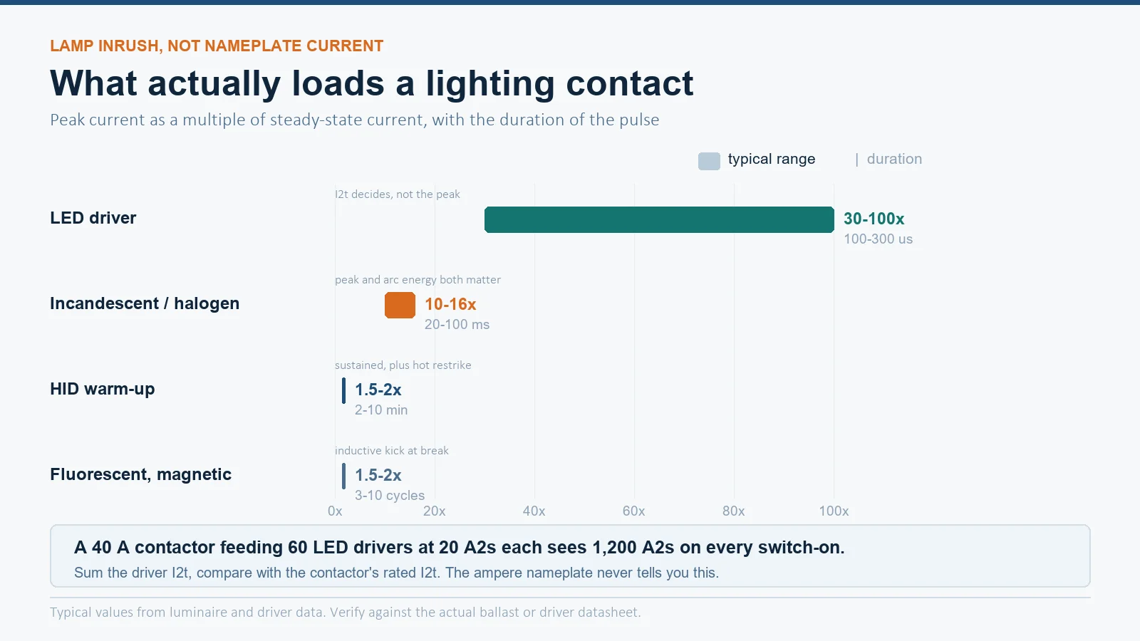
Lamp inrush is the reason lighting contactors are derated in ways that look arbitrary until you see the numbers. A 40 A contactor that switches motor load happily can weld shut on a 40 A tungsten circuit, because the first 30 milliseconds are nothing like steady state.
| Lamp type | Typical inrush vs steady current | Duration | What stresses the contact |
|---|---|---|---|
| Incandescent / halogen | 10–16 × | 20–100 ms, decaying | Peak current and arc energy at break on a hot filament |
| Fluorescent, magnetic ballast | 1.5–2 × | Several cycles | Inductive kick at break, capacitive current with PFC capacitors |
| Fluorescent, electronic ballast | Higher and shorter than magnetic | A few ms | Capacitor charging into the driver front end |
| HID (metal halide, high-pressure sodium) | 1.5–2 × during warm-up | 2–10 minutes | Sustained elevated current, then hot restrike delay |
| LED, constant-current driver | 30–100 ×, very brief | 100–300 µs | Driver capacitor I²t — the number to actually check |
For LED circuits the peak multiple is misleading, because the pulse is too short to heat the contact. The professional check is I²t: take the driver datasheet’s inrush I²t in A²s, multiply by the number of drivers on the contactor, and compare the total against the contactor’s rated I²t. A single 40 A contactor feeding 60 high-bay LED drivers, each with an I²t of 20 A²s, sees 1,200 A²s at every switch-on — and that number, not the 40 A nameplate, is what welds contacts. The same logic underlies the derating rules in contactor derating.
HID is the opposite problem: the current is modest but it stays elevated for minutes, and a hot restrike after a brief interruption can take five to fifteen minutes. That is the single strongest argument for a mechanically latched contactor in a sports hall, a high-bay warehouse or a street-lighting feeder — a two-second voltage dip that drops an electrically held contactor costs far more than the latch mechanism.
Control wiring: two wires or four
The holding method determines the control circuit, and the control circuit is usually where the cost difference actually shows up.
Electrically held, two-wire control. Line voltage or a control voltage goes to A1, neutral or common to A2, and any maintained contact in that path operates the contactor: a wall switch, a photocell, a time clock, a BMS relay output. Removing the voltage opens the contactor. Because the contactor drops out on power loss, a three-wire start-stop station gives you the standard anti-restart behaviour for free — the lights do not come back on by themselves when the supply returns.
Mechanically latched, three- or four-wire control. One momentary pulse on the latch coil closes and locks the contactor; a separate momentary pulse on the unlatch coil releases it. A maintained contact will not do the job: hold the latch coil energised and you burn it out, because it is a momentary-duty coil. So the control chain needs pulse-forming devices — a return-to-centre selector switch, or two interposing relays driven by the BMS with a pulse timer.
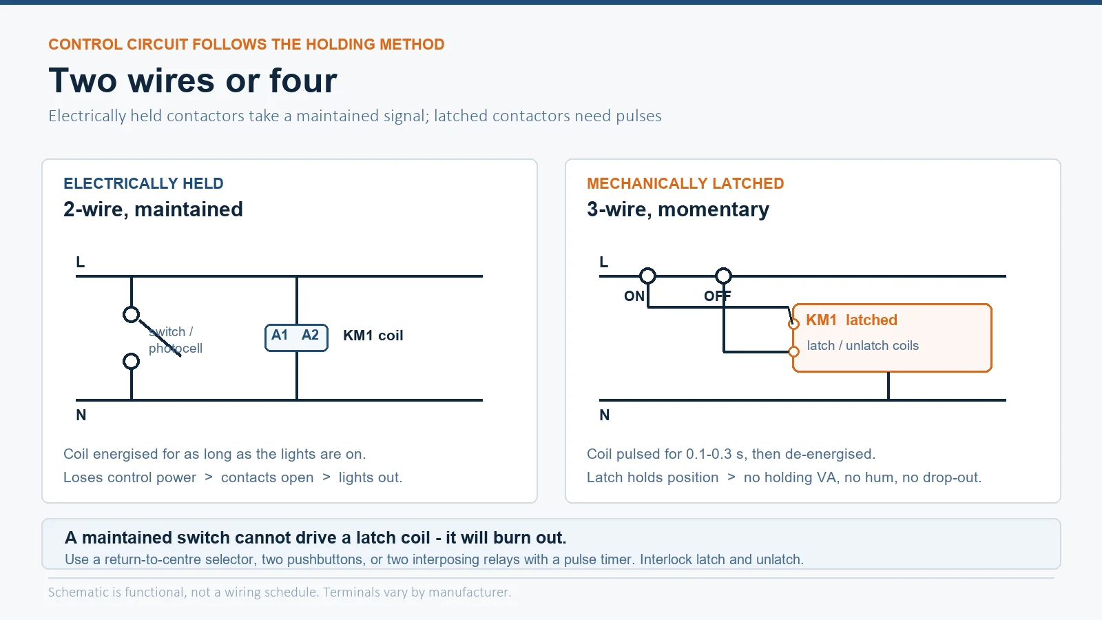
Two details are worth stating because they cause most field problems. First, the latch and unlatch coils must be interlocked so both cannot be energised together; on a polarity-reversing single-coil design that means a changeover contact, not two normally-open contacts in parallel. Second, the pulse must be long enough to complete the latch stroke and short enough not to cook the coil — check the declared pulse range rather than assuming a 0.1 s timer is fine on every frame size. Larger frames need longer pulses.
Voltage, poles and panel layout
Lighting contactor selection is dominated by the site’s lighting voltage, which in commercial buildings is usually a line-to-neutral value rather than the familiar three-phase number:
- 208Y/120 V and 480Y/277 V in the United States — 277 V single-phase lighting circuits are the commercial default, which is why 277 V coils are a stock item.
- 600Y/347 V in Canada — 347 V lighting circuits, and every device in the circuit, including the contactor, must be marked for 347 V.
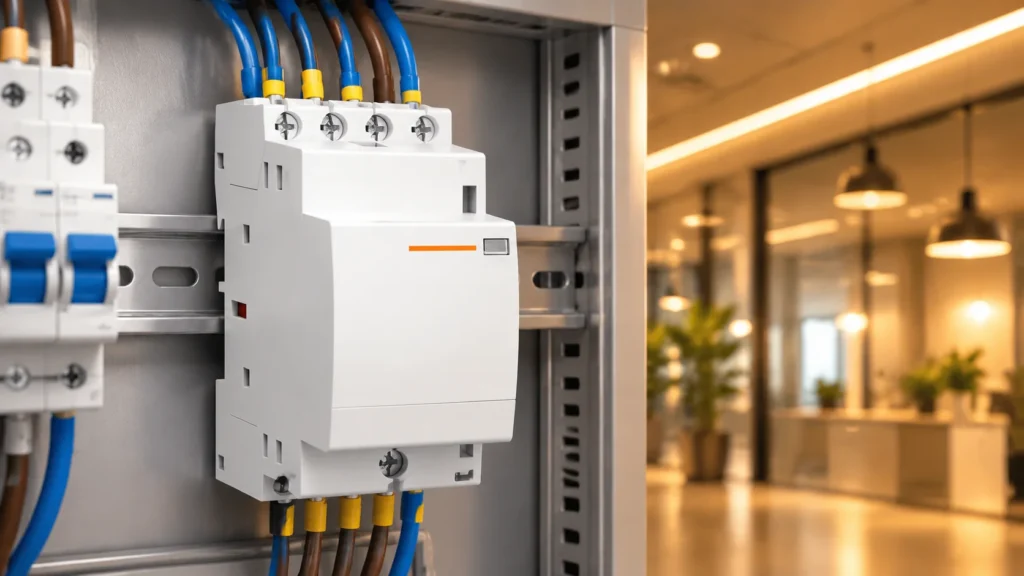
- 230/400 V in IEC markets, where lighting contactors are usually DIN-rail modular devices rated AC-7a and sized in 16 A to 125 A frames.
Pole count follows the circuit topology, not the phase count. A three-phase circuit with a switched neutral needs four poles. Two independent single-phase lighting circuits sharing one contactor need four poles used as two pairs. Where the neutral is solid and only the phases are switched, three poles are enough — but check the specification, because switched neutral is one of the most commonly missed requirements in outdoor, marina and petrol-station lighting.
Panel layout has one rule that is easy to get wrong with mechanically latched devices: they cannot be tested by simply removing control power. Commissioning a panel of latched contactors means proving each latch and each unlatch pulse individually, and labelling which switch does which. Allow for that in the panel schedule. For modular frames and their DIN-rail cousins, types of modular contactors covers how the frame families map onto current ratings.
Choosing between them: four questions
- How long is the contactor held closed each day? Under about four hours a day, the energy and heat argument for a latch disappears and an electrically held unit is the cheaper correct answer.
- What happens if the lights go out unexpectedly? If an unexpected outage is a safety event — an occupied hall, a process area, a security perimeter — you want mechanically latched. If an unexpected re-energisation is the safety event, you want electrically held.
- What kind of lamps? HID banks and large LED banks on long hours push towards latch. Small fluorescent or incandescent zones do not.
- What is driving the coil? A photocell, thermostat or simple time clock drives an electrically held contactor directly. A BMS with a relay output can drive either, but a latched contactor needs the BMS to produce pulses.
ЧАСТО ЗАДАВАЕМЫЕ ВОПРОСЫ
What is the difference between an electrically held and a mechanically held lighting contactor?
An electrically held contactor keeps its power contacts closed only while the coil is energised, so it consumes coil power continuously and opens when control power is lost. A mechanically held (latched) contactor changes state on a momentary coil pulse and is then held closed by a mechanical latch, so it draws no holding power, runs silent, and keeps its last position through a power interruption.
Is a mechanically latched lighting contactor worth the extra cost?
It is when the contactor is closed for most of the day, when the panel contains many contactors, or when an unintended outage is expensive — HID halls that need minutes to restrike, unmanned sites, security lighting. For a small zone switched for a few hours, the latch mechanism will not repay itself.
Can I control a mechanically latched contactor with a normal switch?
Not with a maintained switch. It needs a momentary pulse to latch and a separate momentary pulse to unlatch, which means a return-to-centre selector, two pushbuttons, or two interposing relays with a pulse timer. Holding the latch coil energised will burn it out.
Why does my lighting contactor hum?
An electrically held contactor hums because the coil is energised from an AC supply and the armature responds to the twice-per-cycle force variation. A shaded pole ring keeps it closed but does not silence it. Mechanically latched contactors are silent because the coil is de-energised after the pulse. Persistent loud humming usually means a worn shading ring, a damaged pole face or low control voltage — see contactor buzzing.
Do I need a four-pole lighting contactor?
You need four poles when the neutral must be switched with the phases, or when one device is switching two independent single-phase circuits. Three-phase lighting without a switched neutral needs only three. Check the project specification — switched neutral is a common requirement that is easy to miss.
How do I size a lighting contactor for LED luminaires?
Use the driver’s inrush I²t, not its wattage. Multiply the driver I²t by the number of drivers on the contactor and compare the total with the contactor’s rated I²t. If the manufacturer publishes no I²t figure, ask for it, or split the circuit across more poles so each pole sees fewer drivers.
Can a lighting contactor be used for a motor?
No. It has no overload protection, its contacts are rated for lamp duty rather than motor starting duty, and its coil may be continuous-rated rather than suited to frequent operation. Motor circuits need an AC-3 rated contactor with a thermal overload relay.
What to do next
Decide the holding method first, because it fixes the control circuit and the panel layout. Then fix the pole count from the neutral requirement, then the frame size from the actual load I²t or inrush rather than the steady-state ampere figure. Get those four numbers — holding method, poles, coil voltage and load I²t — and the selection stops being a guess.
For DIN-rail lighting and distribution circuits, the EKMF7 modular contactor from 16 A to 125 A covers the AC-7a household and lighting range with an AC/DC wide-range coil, and the selection logic behind that family is set out in how to choose a modular contactor. For multi-pole panel-mounted lighting feeders, send us the pole count, the lighting voltage, the lamp type and the number of drivers or ballasts per circuit, and we will match the frame and the coil to the circuit instead of to the kilowatt label.