


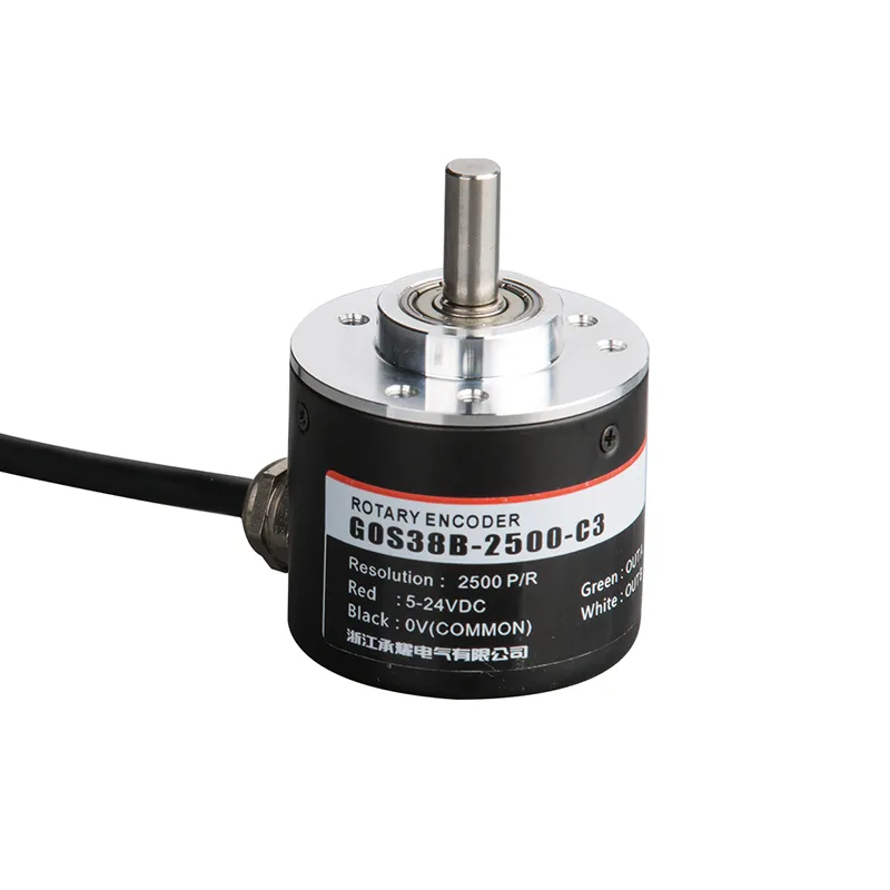
GOS38B Промышленный инкрементальный поворотный энкодер с выходом с несколькими разрешениями
The GOS38B incremental rotary encoder offers reliable and precise position and speed feedback for a wide range of industrial automation applications. Engineered with a robust 38mm diameter housing and solid 6mm shaft, this encoder provides multiple pulse resolutions tailored to meet varied control requirements.
Interested in this product?
Please contact our sales team for the latest pricing, lead time, and technical consultation.
The GOS38B incremental rotary encoder offers reliable and precise position and speed feedback for a wide range of industrial automation applications. Engineered with a robust 38mm diameter housing and solid 6mm shaft, this encoder provides multiple pulse resolutions tailored to meet varied control requirements. Its advanced anti-interference circuitry and rugged design ensure stable performance in harsh environments, making it ideal for motors, conveyors, packaging machinery, and CNC systems. The GOS38B is compatible with multiple control systems, delivering consistent signal output to optimize machine efficiency and accuracy.
Основные характеристики
Incremental rotary encoder with pulse resolutions ranging from 100 to 5000 PPR (pulses per revolution)
Compact 38mm diameter with 6mm solid shaft for versatile installation
Multiple output types: open collector (NPN), push-pull, and complementary outputs
Robust anti-interference circuit for stable and noise-resistant signal transmission
Wide voltage operating range (typically 5-24V DC) suitable for most industrial control systems
High mechanical durability and IP-rated housing for dust and water resistance
Compatible with various automation PLCs and speed controllers
Optional cable lengths and output configurations to customize installations
Преимущества продукции
High precision and resolution improve the accuracy of position and speed control
Durable and compact design withstands rugged industrial environments
Flexible output signals allow integration with various control systems
Advanced anti-interference design reduces signal noise and enhances reliability
Easy installation reduces downtime and maintenance efforts
Supports a wide range of industrial machinery and automation needs
Product model and meaning
| G | 0 | S | 38 | B | 2500 | C | 3 | 2M | ||||
| Категория продукт | Тип продукта | Форма главный вал | Контур продукт | Size of main shaft,shaft hole | Outlet and форма запечатывания | Разрешение | Форма выпуска | Выходной сигнал | Кабель | |||
| G:incremental type | O:megneto- электричество P:photoelec- tricity | S: solid shaft | 38:φ38mm | □:φ6mm 08:φ8mm | B: side outlet metal D:задний металлический выход | 10,20,50, 60,100, 200,360, 400,500, 600,800, 1000,1024,1200,200,2048,2500,3000,3600,5000
| M:analog quantity output C:выход с открытым коллектором F:дополнительный выход T:push pulloutput L:выход преобразователя 5 В A:24V drive output | 1:phase A signal 2:phase AB signal 3:фазовый сигнал ABZ 4:ABA/B/ signal 5: phase ABZA/B/Z/ signal 6:420mA 7:0-5V 8:0-10V | 2Default 2m линия, для не 2м, маркировка достаточно | |||
Таблица проводов
| Цвет линии | C/F/T output signal | Цвет линии | L/A output signal | Цвет линии | M signal(current) | Цвет линии | M signal(voltage) | |||
| красный | Vcc | красный | Vcc | Коричневый | Vcc | Коричневый | Vcc | |||
| черный | 0V | черный | 0V | белый | 0V | белый | 0V | |||
| зеленый | Aphase | зеленый | Aphase | зеленый | 1 | зеленый | +U | |||
| белый | Фаза B | белый | Фаза B | yellow | -1 | yellow | -U | |||
| yellow | Фаза Z | yellow | Zphase | щит | F -G | щит | F -G | |||
| щит | F -G | коричневый | A/phase | |||||||
| gray | B/phase | |||||||||
| апельсин | Z/phase | |||||||||
| щит | F -G |
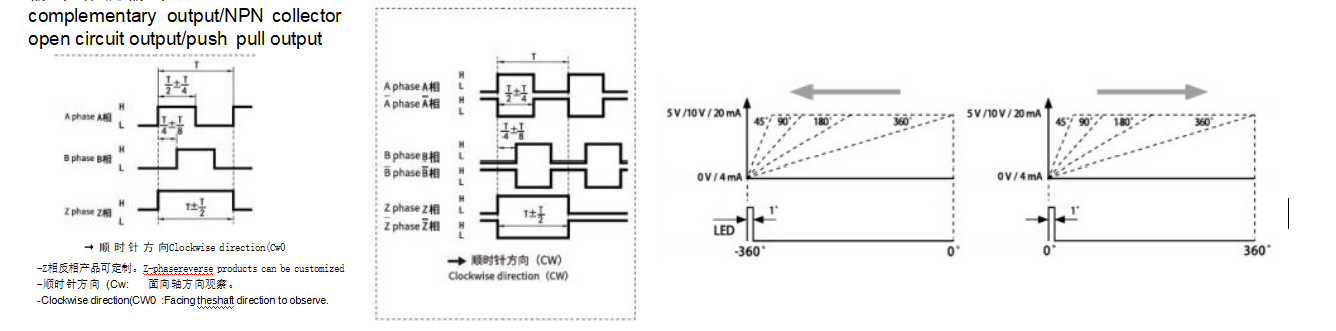
Output phase difference
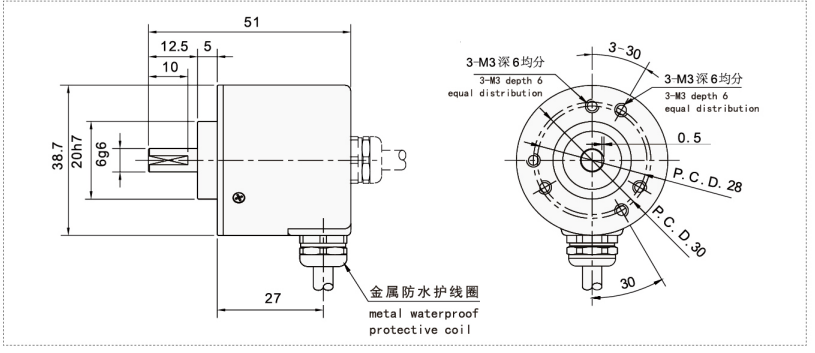
Mechanical drawings(mm)
Сценарии применения
Motor speed and position feedback in industrial automation
Conveyor belt speed monitoring and control
Packaging machinery synchronization and operation
CNC equipment position sensing
Robotics for joint angle and rotational feedback
Printing machinery and assembly line automation
Installation & Maintenance
Ensure the shaft of the encoder matches the application’s coupling diameter (6mm solid shaft).
Align the encoder shaft precisely with the machine shaft; use flexible couplings to avoid misalignment stress.
Securely mount the encoder with the provided hardware to minimize vibration.
Connect power supply within the recommended voltage range (5-24V DC) following the wiring diagram.
Use shielded cables for signal wiring to prevent electromagnetic interference.
Perform regular cleaning to remove dust and debris; avoid using harsh chemicals or water jets.
Check wiring and connectors periodically for secure connections and signal integrity.
Replace the encoder if signs of mechanical wear or unstable signals arise.