Motor Thermal Damage Curve vs Relay Trip Curve
Six points, two lines, three conditions. Plot the thermal damage curve against the relay trip curve and know exactly what the overlaps mean.
Read More
Two architectures can stop a motor safely, and they are not interchangeable. One opens contactors and physically removes power from the motor. The other tells the drive’s electronics to stop firing the output stage, so the motor produces no torque while its terminals remain live. Both can satisfy a safety function; only one gives you galvanic isolation, and only one has wearing parts.
This is an architecture decision, not a component decision. If you are still choosing between a safety contactor and a standard contactor, that comparison is in safety versus standard contactors. This article assumes the safety function has already been defined and asks how to implement it: Safe Torque Off from the drive, a contactor-based power removal circuit, or the hybrid arrangement that most machine builders settle on.
| STO (drive-integrated) | Contactor safe stop | |
|---|---|---|
| What is removed | Gate pulses to the output stage — no torque produced | Supply voltage to the motor — no energy delivered |
| Motor terminals | Remain live; dangerous voltage present | Isolated from the supply |
| Galvanic isolation | No | Yes |
| Typical response | Milliseconds — no moving parts | Tens of milliseconds, longer with coil suppression |
| Wear parts | None | Contacts, coil, mechanism |
| Diagnostics | Internal self-test, status word to the controller | Mirror contacts, external device monitoring (EDM) |
| Retrofit to existing drives | Not possible without replacing the drive | Possible on almost any drive |
| Isolation for maintenance | Still requires a separate disconnect | Provides it, but lockout procedure still applies |
The most expensive misconception in this area is treating STO as isolation. STO makes the motor safe to touch only if the motor cannot generate torque — it does not make the motor terminals dead. Anyone opening a motor terminal box after an STO stop is working on live conductors.
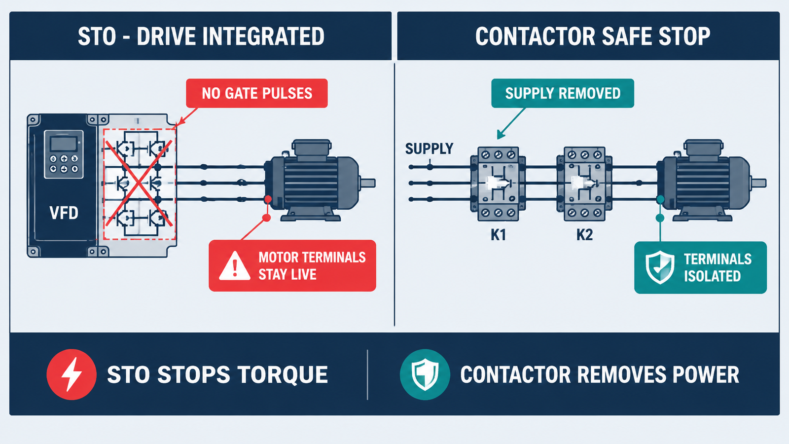
Safe Torque Off is a function inside the drive. When the safety input is de-asserted, the drive’s control electronics stop generating the switching pattern for the power semiconductors, so no rotating field is produced and the motor cannot generate torque. The drive typically certifies this function to SIL 3 / PL e as a subsystem; whether the whole machine achieves that level depends on the sensors, wiring and verification around it.
Three properties define its use:
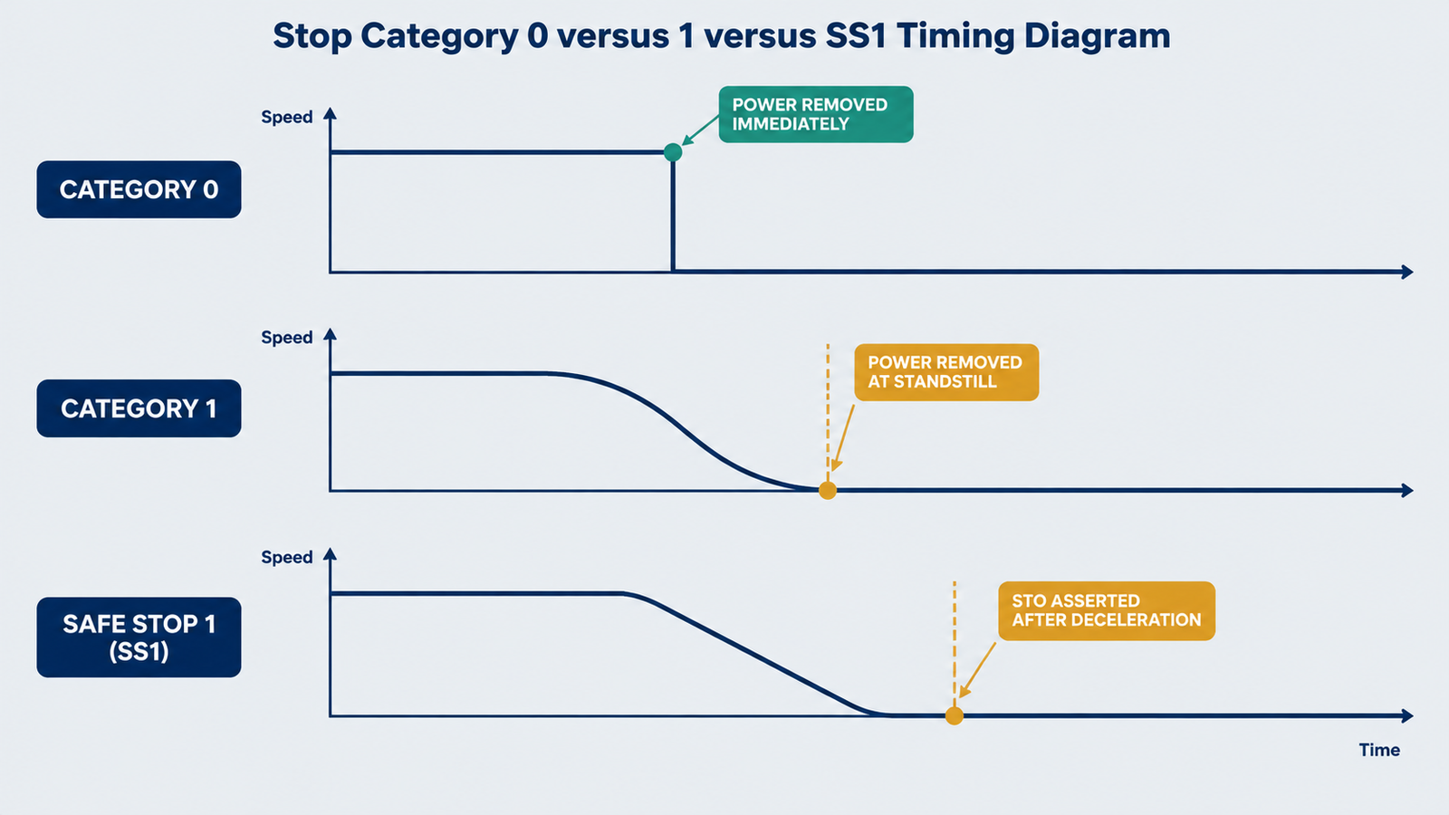
Most drives pair STO with a controlled deceleration: the standard safety function SS1 (safe stop 1) commands a controlled stop, monitors that the motor actually decelerates, and then asserts STO. That combination gives you a controlled stop without wear, and it is why pure STO is less common in practice than SS1-on-STO.
A contactor-based safe stop removes the supply. The conventional implementation uses two contactors in series, each with mirror (force-guided) contacts, energised through a dual-channel safety relay or safety PLC with external device monitoring. Two devices in series exist to defeat a single welded contact: one contactor that fails closed still leaves a second device able to open the circuit.
The advantages are equally concrete:
The cost is mechanical: contacts wear, coils fail, and the drop-out time is not negligible. That last point interacts directly with coil suppression — a plain flyback diode on a DC coil can extend drop-out by a factor of six to ten, which may push the safety function’s response time outside its specification. The numbers are in contactor coil surge suppression, and this is the single most common reason a contactor-based safety circuit fails its validation on the bench.
IEC 60204-1 defines stop categories, and the category constrains the architecture before any device is chosen:
| Category | Behaviour | Typical implementation |
|---|---|---|
| Category 0 | Uncontrolled stop — power removed immediately | Contactor drop-out, or STO on a drive without braking |
| Category 1 | Controlled stop, then power removed when standstill is reached | Drive decelerates, then contactor opens (or STO asserted) |
| Category 2 | Controlled stop with power maintained | Drive-controlled stop only; not a power-removal function |
Category 0 on a high-inertia load means mechanical stress and, on a vertical axis, a load that may not hold. Category 1 needs a controlled deceleration path, which means the drive must stay powered and in control during the stop — a requirement that a contactor-only architecture cannot satisfy, because opening the contactor removes the drive’s ability to brake. This is where STO earns its place: it can be asserted after a controlled stop, with the drive still powered throughout.
| Situation | Best fit | Причина |
|---|---|---|
| New single-axis machine, STO-capable drive | SS1 on STO | Controlled stop, no wear parts, strong diagnostics |
| Retrofit on drives without a safety input | Contactor pair with mirror contacts | The only practical option without replacing drives |
| Several motors fed from a common group | Contactor pair | One break covers the whole group; STO is per drive |
| Vertical axis or unbalanced load | STO plus a brake, or contactor plus a brake | Neither architecture holds a load on its own |
| Maintenance isolation required at the motor | Contactor pair plus a disconnect | STO leaves terminals live; isolation is a separate requirement |
| Press, shear or hoist with category 1 stop | Hybrid: SS1 on STO plus contactor backup | Controlled stop with a redundant power-removal channel |
| Space-constrained cabinet on a servo axis | STO | No contactors, no arc chutes, less panel volume |
The hybrid arrangement deserves a note because it is frequently the right answer and rarely the first one proposed. Pairing SS1-on-STO with a contactor backup gives a controlled stop and a redundant power-removal path, at the cost of one contactor pair and its wiring. On machines where a runaway after a safety stop is the dominant risk, that redundancy is usually justified; on a simple conveyor it is usually not.
Where the drive is being fed through a combination starter, the contactor may already be performing a switching duty that should not be conflated with the safety function — the distinction between a combination and non-combination starter is covered in combination versus non-combination starters, and the general starter selection context in contactor selection for motor starters.
| Mistake | Consequence | Correction |
|---|---|---|
| Treating STO as electrical isolation | Live motor terminals during maintenance | Keep a separate disconnect and lockout procedure |
| Assuming STO holds a vertical load | Load drops when torque is removed | Add a brake and verify it independently |
| Single contactor with a mirror contact as the only channel | No redundancy; one welded contact defeats the function | Two contactors in series, or a certified single-channel device |
| Plain flyback diode on a safety contactor’s DC coil | Drop-out 6–10× slower; response time out of specification | Diode-plus-Zener or MOV, sized for the required drop-out |
| No EDM on a contactor safety circuit | Welded contactor discovered only at the next demand | Wire mirror contacts to the safety relay’s EDM input |
| Automatic reset after a safety stop | Machine restarts into the hazard zone | Manual, monitored reset outside the hazard zone |
One further constraint applies to the contactor itself: a latching or mechanically held contactor must never be used as the safety element, because it does not open on power loss. The mechanisms and their failure modes are described in latching and reversing contactor types.
Neither is inherently safer; each is certified to a level, and the application determines whether that level and the architecture are adequate. STO has no wearing parts and better diagnostics, but no isolation. A contactor pair isolates and works on any drive, but adds wear and drop-out time. Compare achievable performance level and functional suitability, not brand preference.
For stopping torque, yes — if the drive is STO-capable and the risk assessment accepts an architecture without galvanic isolation. For isolation during maintenance, no: a disconnect is still required, and many machine standards expect a physical means of isolation independent of the drive.
It removes torque immediately, but it does not stop motion. A coasting load continues under inertia, and a vertical load may fall unless a brake engages. Stop category 0 behaviour is the result unless the drive is commanded to decelerate first.
Conventionally two, in series, each with mirror contacts, monitored by a dual-channel safety relay with EDM. A single contactor is only acceptable when a certified device rated for the required category is used and the risk assessment supports it.
Check the coil suppression first. A plain flyback diode on a DC coil can extend drop-out by six to ten times, which is usually enough to break the response-time budget. Replacing it with a diode-plus-Zener combination or an MOV restores the speed while keeping the protection.
Yes, and that is one of its advantages: a contactor pair upstream of a group removes power from every motor on that group at once. STO cannot do this because it is a function of each individual drive.
Decide the stop category first, then the architecture, then the devices. If the machine needs a controlled stop with power maintained during deceleration, the drive has to stay in control — which points to SS1 on STO, with a contactor pair added only if a redundant power-removal channel is justified. If the drives are older, the motors share a group, or isolation at the motor is a requirement, a contactor pair with mirror contacts and EDM is the right answer. In both cases, keep the disconnect, keep the brake, and check the drop-out time before signing the validation. For contactors used in the power-removal path, the CJX2-D / LC1-D series page lists the frame and auxiliary configurations, and the AC contactor category covers the range.