AC-15 vs DC-13: Auxiliary Contact Ratings Explained
AC-15 gives a contact 4 A at 240 V; DC-13 gives the same contact 0.3 A at 250 V. The categories, the test duties behind them, and the PLC dry-circuit floor.
Read More
“3-phase motor starter with overload protection” is one of the most-searched sourcing phrases in motor control — and one of the most misunderstood. A starter is not a contactor with a bigger label; it is a tested chain of five parts whose ratings must match each other and the motor nameplate. Size any link from the wrong number and the failure is silent: the breaker rides through the overload, the motor cooks, and nobody trips. This page walks the four-step sizing chain with worked numbers, then lists the five mistakes that survive commissioning.
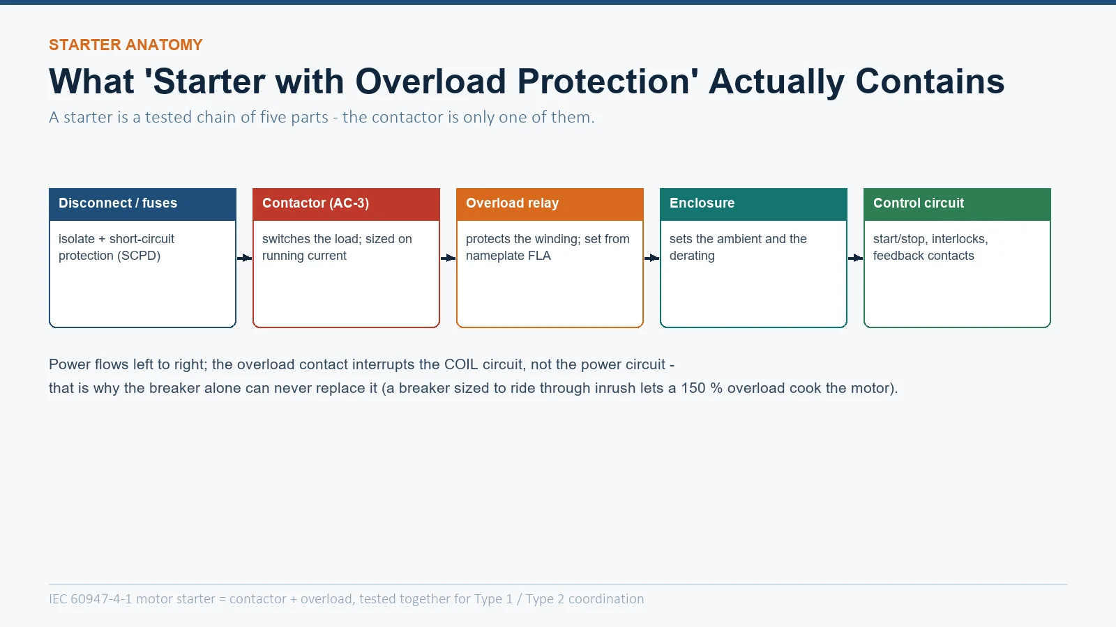
| المكوّن | Job | Sized from |
|---|---|---|
| Disconnect + fuses / breaker | Isolation and short-circuit protection (SCPD) | NEC table FLC or IEC fuse tables |
| Contactor (AC-3) | Switches the running load | Nameplate FLA at the actual voltage |
| Overload relay | Protects the winding from overload | Nameplate FLA (not the table!) |
| Enclosure | Sets the ambient and the derating | Environment, IP/NEMA class |
| Control circuit | Start/stop, interlocks, feedback | Machine function |
The key division of labor: the SCPD clears short circuits, the overload relay clears overloads. A breaker sized to survive inrush (up to 250 % of FLA) will happily let a 150 % overload cook a motor for minutes — the overload contact stops that by interrupting the coil circuit, not the power circuit. That is why the contactor-in-a-starter role in our contactor selection guide is only one link of the chain.
Everything downstream starts from the motor’s nameplate full-load amps (FLA) at the voltage and connection actually wired. Two traps:
Select the contactor so its AC-3 rated operational current at your voltage meets or exceeds the FLA, with duty and ambient checked on top. The mechanics of reading Ie tables are in our AC-3 rating chart guide; the utilization-category logic behind AC-3 is in the AC-1 to AC-4 explainer. Two conditions push the frame up from the paper answer: plugging/jogging duty (AC-4 territory, see the AC-3 vs AC-4 comparison) and hot enclosures — a 45 °C panel already eats 5–10 % of the AC-3 rating.
Two decisions here: the dial setting and the trip class.
Setting. IEC practice is to set the dial at nameplate FLA and let the relay’s curve provide the margin. NEC 430.32(A)(1) caps the setting: 125 % of FLA for motors with marked service factor ≥ 1.15 or marked temperature rise ≤ 40 °C, otherwise 115 % — with 140 %/130 % escape values under 430.32(C) only if the motor cannot start at the lower setting. The dial discipline and nuisance-trip causes are covered in our overload field setting guide.
Trip class. The class number is the trip time at 7.2× setting under IEC 60947-4-1: Class 10 trips within 10 s (pumps, fans), Class 20 within 20 s (high-inertia loads), Class 30 within 30 s (long accelerations). Match the class to the measured start time — the thermal-damage curve logic is in our motor thermal damage vs relay trip curve guide.
The contactor and overload must be protected by an SCPD rated for the available fault current, and the pair must be a tested combination:
When the disconnect, SCPD, contactor and overload ship in one certified box, that is a combination starter — the architecture options are compared in our combination vs non-combination starter guide.
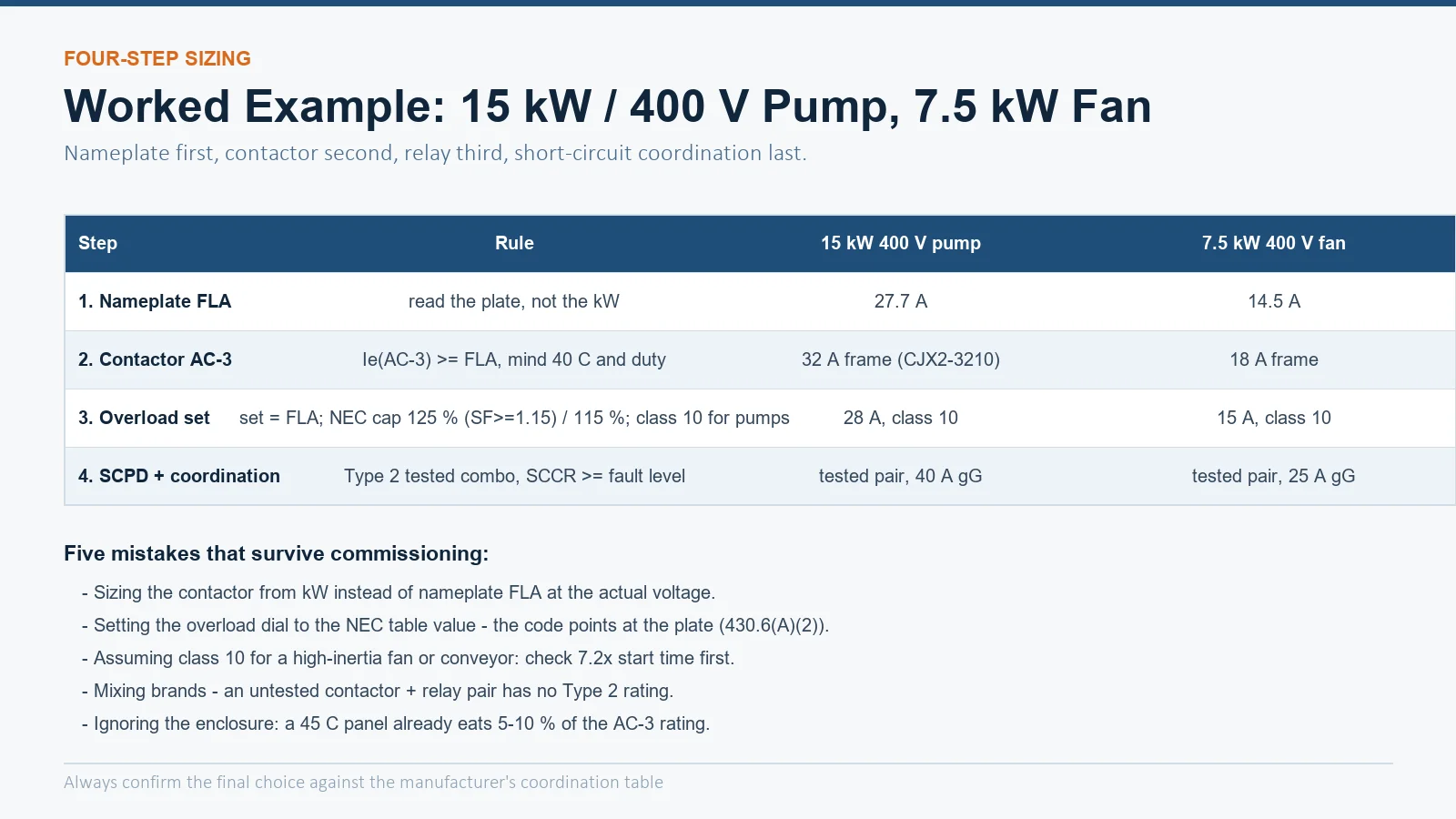
| الخطوة | Rule | 15 kW / 400 V pump | 7.5 kW / 400 V fan |
|---|---|---|---|
| 1. Nameplate FLA | plate, not kW | ≈ 27.7 A | ≈ 14.5 A |
| 2. Contactor AC-3 | Ie ≥ FLA, check duty + ambient | 32 A frame (e.g. CJX2-3210) | 18 A frame |
| 3. Overload | set = FLA (NEC cap 125 %/115 %); class per start time | 28 A, Class 10 | 15 A, Class 10 |
| 4. SCPD + coordination | tested pair, SCCR ≥ fault level | 40 A gG, Type 2 | 25 A gG, Type 2 |
Both examples assume 4-pole induction motors at nameplate; a hot enclosure or frequent starting pushes both selections up a frame — the interactions are the same ones our duty cycle guide quantifies. For the switching component itself, the CJX2 series 3-phase AC contactor covers the 9–95 A starter range, with the wider frames in the AC contactor category.
| Mistake | Consequence |
|---|---|
| Sizing the contactor from kW instead of nameplate FLA | Under-rated at low-voltage/high-current sites; overheated poles |
| Setting the overload from the NEC table value | Protection 10–15 % looser than the motor’s real thermal capacity |
| Class 10 default on a high-inertia drive | Nuisance trips on every start — or a bypassed relay (worse) |
| Mixing brands without a coordination test | No Type 2 or SCCR rating; motor damage and warranty gaps after a fault |
| Ignoring the enclosure ambient | Everything inside derates; summer trips and shortened contact life |
The four-step sizing holds for a plain DOL starter, but reduced-voltage and reversing schemes redistribute the currents, and each has one sizing trap:
| Starter type | What carries the current | Sizing consequence |
|---|---|---|
| Reversing (DOL) | Two contactors, one per direction | Each contactor sees full FLA — same frame as DOL, plus mechanical/electrical interlock; see our reversing wiring guide |
| Star-delta | Line contactor and delta contactor carry phase currents; star contactor carries 1/√3 of line current | Delta contactor sized at 0.58 × FLA (AC-3), star contactor smaller; the overload sits in the windings on some layouts — set it to winding current, not line current |
| Part-winding | Two contactors energized in sequence | Each half-winding carries its own FLA share during transition; verify the transition timing against the motor maker’s data |
The star-delta row hides the most common field error: the overload relay is set to nameplate FLA even though it sits in a path that only ever sees winding current (or the reverse, depending on layout). Follow the manufacturer’s wiring diagram for where the relay senses, then set the dial to the current that path actually carries — the nameplate current is the anchor, not always the dial value. The coil-side implications of switching two contactors in sequence (control wiring, feedback, dead time) are the same ones covered in our contactor wiring guide.
Yes, for any motor that can overload. The breaker or fuses clear short circuits; the overload relay is the only device protecting the winding from a slow overload. The combination is the defining feature of a motor starter.
At 400 V a 15 kW 4-pole motor draws roughly 27–29 A on the nameplate, so a 32 A AC-3 frame is the normal answer — but confirm from the plate and re-check for plugging duty, hot enclosures and altitude, any of which can push the selection to 40 A.
Class 10 covers most pumps, fans and machine tools that reach speed in a few seconds. Choose Class 20 for loaded conveyors, large fans and compressors with starts beyond 10 s, Class 30 for extreme inertia. Verify with a measured start time at 7.2× current rather than assuming.