En contactor vs control relay distinction is one of the most frequently misunderstood topics in industrial control panel design. Both are electromechanical switching devices that use a coil to move contacts, yet they serve fundamentally different circuit roles. A contactor is built to make and break power circuits — motor loads, heater banks, and large lighting branches — while a control relay switches control circuits such as logic signals, interlocks, and pilot devices. Choosing the wrong device can lead to welded contacts, nuisance failures, and code violations. This guide explains the differences clearly and gives practical selection guidance for panel builders, OEM engineers, and maintenance teams.
What Is a Contactor?
A contactor is an electrically operated switch designed for frequent make-and-break operation on power circuits. When you energize the coil, the magnetic field pulls the armature, closing the main contacts and completing the load circuit. De-energizing the coil opens the contacts and interrupts the load current. To understand the device in more depth — including its internal parts and working principle — see the complete contactor fundamentals guide.
Contactors are characterized by:
High current capacity: typically 9 A to over 1000 A, rated for continuous and inrush motor currents
Arc suppression: built-in arc chutes that divide, cool, and extinguish arcs when interrupting inductive loads
Normally-open main contacts: the power path fails open on control power loss, a critical safety feature
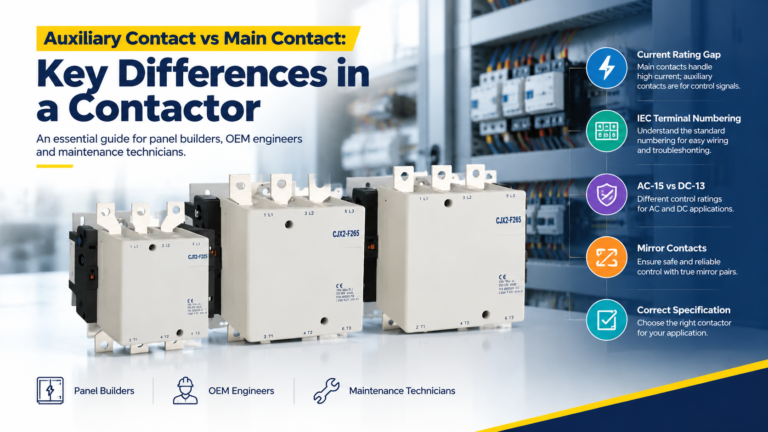
Auxiliary contacts: optional NO/NC blocks for status feedback and interlocking
Standard compliance: designed per IEC 60947-4-1 or UL 508
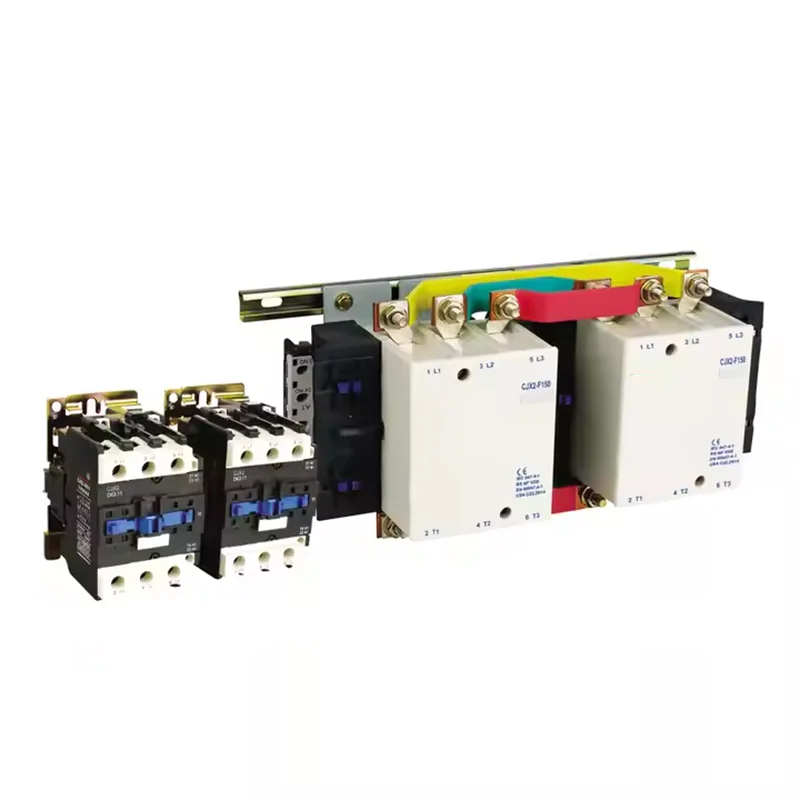
Contactors are always the final switching element in a motor branch — the device that directly carries and interrupts the load current. For applications requiring reversible motor operation, consider a mechanical interlocking contactor like the CJX2-F400, which prevents simultaneous closing of forward and reverse contactors.
What Is a Control Relay?
A control relay is an electromagnetic switching device built for control circuits rather than power circuits. It uses a low-power coil signal to operate one or more contacts that switch logic-level loads — PLC inputs, indicator lamps, timer triggers, interlock chains, or the coils of larger devices including contactors. Control relays are specified under IEC 61810 and typically handle currents from 0.1 A to 10 A.
Key characteristics include:
Flexible contact arrangements: SPDT, DPDT, multiple NO/NC, or changeover configurations
Fast switching speed: 1–20 ms operate time, compared with 50–100 ms for contactors
Compact size: designed for DIN rail density in control panels
Minimal arc suppression: contacts are not engineered to interrupt motor inrush or inductive arcs
High mechanical life: often 10–100 million operations
Contactor vs Control Relay: Key Differences
The table below summarizes the most important technical distinctions:
Parámetro
Contactor
Control Relay
Primary circuit role
Power-load switching
Control-logic switching
Current rating
9–1000+ A
0.1–10 A
Arc suppression
Built-in arc chutes
Minimal or none
Contact configuration
NO main + optional auxiliaries
NO, NC, changeover, multiple poles
Switching speed
50–100 ms
1–20 ms
Standard
IEC 60947-4-1
IEC 61810
Typical load
Motor, heater, lighting bank
PLC signal, interlock, indicator
Cost range
$50–500+
$5–100
The most critical difference is circuit role, not current rating alone. Two devices may share the same headline ampere value, but a contactor’s contacts are specifically engineered to handle the arc energy from interrupting an inductive motor load, while a relay’s contacts are not. A 9 A contactor costs more than a 20 A relay precisely because of this arc-quenching engineering.
When to Use a Contactor
Use a contactor whenever the switched load is a power circuit:
Three-phase motor starting: direct-on-line (DOL), star-delta, and reversing starters all require contactors rated for the motor’s full-load current and inrush
HVAC compressors and chillers: frequent cycling under inductive load demands arc-rated contacts
Industrial heating elements: resistive loads with high steady-state current
Capacitor banks: power factor correction circuits need contactors rated for capacitor switching duty
Large lighting circuits: stadium lighting, street lighting, or high-bay LED arrays
When sizing a contactor for motor applications, verify the full-load current, starting method, and utilization category (AC-3 for squirrel-cage motor starting). The detailed contactor sizing and selection guide walks through this calculation step by step. For a deeper understanding of utilization categories like AC-1 through AC-4, refer to the IEC 60947-4-1 category reference.
When to Use a Control Relay
Use a control relay when the switching task involves logic, signaling, or control-circuit interfacing:
PLC output expansion: when a PLC’s onboard output cannot directly drive a contactor coil, a relay provides the interface
Voltage level conversion: translating a 24 V DC PLC signal to a 230 V AC control bus
Alarm and status aggregation: collecting fault signals from multiple devices into a common output
Indicator lamp driving: switching pilot lights and annunciator panels
Control relays excel in multi-circuit logic where a single coil can simultaneously make and break several independent contacts, enabling complex automation sequences in a compact footprint.
Using Both: The Interposing Relay Architecture
In many industrial panels, contactors and control relays work together in a tiered architecture:
PLC or sensor → control relay → contactor coil → contactor main contacts → motor
The control relay handles the logic interface — isolating the PLC output, multiplying contacts, or converting voltage levels. The contactor handles the heavy power switching. This separation protects sensitive PLC outputs from the inrush and flyback energy of a contactor coil, while allowing the contactor to manage the motor load within its rated duty.
A direct PLC-to-contactor connection is possible when the PLC output meets the coil’s voltage, inrush, steady-state, and transient-suppression requirements. When those conditions are not satisfied, an interposing relay is the correct and standard solution.
Common Selection Mistakes
Using a control relay for motor power: the resulting arc welds contacts shut, creating a dangerous failure where the motor cannot be stopped. Always match the device to the load type.
Omitting overload protection: neither a contactor nor a relay provides overload or short-circuit protection by itself. A thermal overload relay or motor protection circuit breaker must accompany the contactor in a motor branch. See the contactor wiring guide for the correct protection chain.
Confusing auxiliary contacts with control relays: the auxiliary block mounted on a contactor provides status feedback, not independent logic. If you need multiple changeover contacts for complex logic, use a dedicated control relay.
Ignoring utilization categories: a contactor rated for AC-1 (resistive load) may fail prematurely on AC-3 (motor starting) duty. Always verify the category matches the application.
For another common comparison that trips up specifiers, see the breakdown of contactor vs circuit breaker — switching duty versus protection.
Preguntas frecuentes
Can a control relay replace a contactor?
No. A control relay cannot safely interrupt motor inrush current or the arc energy from an inductive load. Even if the relay’s headline current rating appears sufficient, its contacts lack the arc-quenching design required for power-circuit duty. Attempting this leads to welded contacts and potential safety hazards.
What is the current boundary between contactors and relays?
There is no universal threshold. Industrial practice often cites 9–10 A as a rough guide, but the true selection criterion is circuit role and load type, not current alone. A 6 A motor still requires a contactor because of inrush and arc energy, while a 10 A resistive indicator circuit may use a relay.
Do contactors provide overload protection?
No. Contactors switch the load; they do not protect it. Overload protection requires a separate thermal or electronic overload relay, and short-circuit protection requires a fuse or circuit breaker. The contactor, overload, and protection device form a coordinated motor starter assembly.
Can I use the same contactor for AC and DC loads?
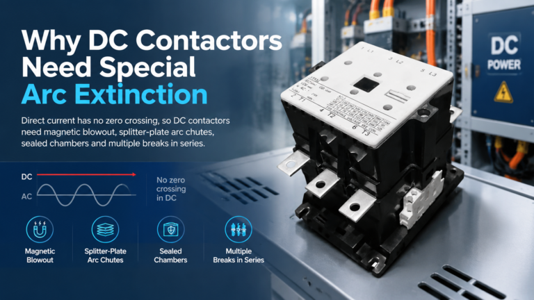
Only if the manufacturer explicitly rates the contactor for the intended DC application. DC arcs are harder to extinguish than AC arcs because there is no natural current zero crossing. Verify the DC voltage, current, and utilization category before applying a contactor to a DC load.
Conclusión
The contactor vs control relay decision comes down to circuit role. Contactors switch power — motors, heaters, capacitor banks — with arc-rated contacts built for inductive duty. Control relays switch logic — PLC signals, interlocks, and indicators — with fast, flexible, multi-contact configurations. In most industrial panels, both devices work together: the relay processes the command, and the contactor handles the load. Select each by its circuit function, verify ratings against the actual load, and always include coordinated overload and short-circuit protection in motor branches. For specific product needs, explore the CJX2-F400 mechanical interlocking contactor or browse the full contactor range to match your application.
DC contactors need special arc extinction because DC current has no natural zero crossing. See how magnetic blowout, arc chutes and series breaks kill a DC arc — and how to specify one correctly.
Main contacts carry the motor current; auxiliary contacts carry control signals. Learn the real rating gap, IEC terminal codes, and how to spec both correctly.
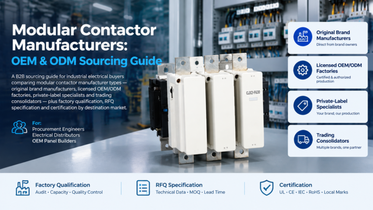
A sourcing guide to modular contactor manufacturers: match the four supplier archetypes, qualify any factory with a nine-point framework, and send an RFQ that gets comparable quotations.