How to Size & Select a Contactor: Motor Power, AC-3 & Sizing Chart
Published: Author: Lisa
Why Sizing a Contactor Correctly Matters
How to size and select a contactor for a three-phase motor is one of the most common questions in industrial panel building. The right contactor switches the motor cleanly, lasts for years, and keeps the overload relay doing its job. The wrong one overheats, welds its contacts, or fails after a few thousand operations.
In this guide you will learn how to match a motor’s power and full-load current to a contactor’s AC contactor rating, when to add a safety margin, and how to read a sizing chart. We also include a worked example and a printable chart based on IEC 60947-4-1 AC-3 values.
What AC-3, AC-1 and AC-4 Mean (IEC 60947-4-1)
Contactors are grouped by utilization categories. These categories describe the loads the contacts can break and make repeatedly without excessive wear.
AC-1 — non-inductive or slightly inductive loads such as heaters, resistors, or incandescent lamps. The current is steady, so contact erosion is low.
AC-3 — squirrel-cage motors: normal starting, stopping, and running with the motor up to speed before the contacts open. This is the category you need for most motor starters.
AC-4 — squirrel-cage motors with frequent inching, jogging, or plugging . The contactor closes onto a stationary or counter-rotating motor, so inrush current is much higher and contact wear is severe.
For a standard pump, fan, conveyor, or compressor, choose an AC-3 rated contactor. If the application involves repeated jogging, step up to an AC-4 rated unit or select the next larger AC-3 frame. You can read more about the differences in our AC-3 vs AC-4 utilization category guide.
The Two Numbers You Need from the Motor Nameplate
Before you open a catalog, copy these two values from the motor nameplate:
Motor power (kW or HP) — usually given for a reference voltage such as 400 V / 50 Hz or 460 V / 60 Hz.
Full-load current (FLC or FLA) — the steady-state current the motor draws at rated load and voltage.
Also note the operating voltage, frequency, duty cycle, and whether the motor is direct-on-line (DOL) or star-delta started. A star-delta starter uses three contactors, but each contactor only carries 58 % of the motor FLC in the run state, so sizing changes slightly.
Step-by-Step: How to Size a Contactor
Follow this sequence for a conventional DOL motor circuit:
Record the motor FLC at the voltage in your panel. Do not guess from kW alone.
Choose a contactor whose AC-3 current rating is equal to or greater than the FLC. IEC 60947-4-1 ratings are given in amperes and are per phase.
Add a 10–25 % margin. For continuous duty, ambient temperatures above 40 °C, dusty cabinets, or frequent switching, size the contactor to at least 1.25 × FLC.
Check the kW rating table at your supply voltage. The kW and FLC ratings must both be satisfied; one does not override the other.
Select the coil voltage to match your control circuit (commonly 24 V, 110 V, 220 V, or 380 V AC).
Count auxiliary contacts. Decide how many normally-open (NO) and normally-closed (NC) contacts you need for interlocks, indicators, and PLC inputs.
Verify coordination type with the upstream breaker or fuses. Type 2 coordination means the contactor is still fit for service after a short circuit; Type 1 allows damage but no danger to personnel.
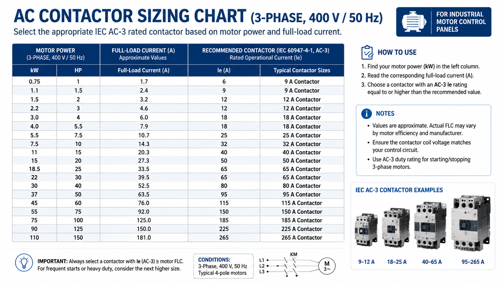
AC Contactor Sizing Chart (3-Phase, 400 V / 50 Hz)
Use the table below as a quick reference for IEC AC-3 contactor selection. FLC values are typical; always confirm against the motor nameplate.
Motor kW
Typical FLC (A)
Recommended AC-3 Current (A)
Common Frame*
0.37
1.1
9
09
0.75
2.0
9
09
1.5
3.6
12
12
2.2
5.0
18
18
3.0
6.5
25
25
4.0
8.5
32
32
5.5
11.5
38
38
7.5
15.5
40
40
11
22
50
50
15
29
65
65
18.5
35
80
80
22
41
95
95
30
55
115
115
37
66
150
150
45
80
185
185
55
97
225
225
75
132
265
265
90
160
330
330
110
195
400
400
*Frame numbers are common IEC contactor current ratings, not a single manufacturer’s part number.
When to Move Up One Frame Size
Even when the chart says a 25 A contactor is enough, move up one frame if any of the following apply:
Frequent switching — more than a few hundred operations per hour.
Jogging or plugging — use AC-4 or oversize the AC-3 unit.
High ambient temperature — contactors are normally rated at 40 °C; derate above that.
Poor ventilation or dusty enclosure — heat cannot escape, so current capacity falls.
Voltage dip on start — long cable runs or weak supply can extend inrush time.
Future motor upgrade — a slightly larger contactor saves rewiring later.
Common Contactor Sizing Mistakes
Sizing by kW alone. A 7.5 kW motor at 230 V draws twice the current of the same motor at 460 V. Always check FLC at the actual voltage.
Ignoring inrush current. DOL starting pulls 6–8 × FLC for a short time. The contactor must be able to make and break this current.
Wrong coil voltage. A 220 V coil on a 380 V control circuit burns out quickly.
Forgetting auxiliaries. Running out of NO/NC contacts leads to extra relays and wiring.
No coordination check. During a short circuit, an undersized contactor can weld shut or disintegrate.
Worked Example: 11 kW, 400 V Motor
Suppose you have an 11 kW three-phase motor running on 400 V / 50 Hz. The nameplate FLC is 22 A.
FLC = 22 A.
Select AC-3 rating ≥ 22 A. A 25 A contactor technically works, but with a 25 % margin you want 1.25 × 22 = 27.5 A, so choose a 32 A frame or larger.
Check the kW table: an 11 kW / 400 V motor falls in the 25–40 A range; a 32 A or 40 A AC-3 contactor is a comfortable choice.
Choose coil voltage to match your control transformer.
Add the overload relay sized to the motor FLC, not the contactor rating.
For this size of application our CJX2 series 3-phase AC contactor is available in frames from 9 A to 800 A, with coil voltages from 24 V to 660 V and bolt-on auxiliary contact blocks.
Related Contactor Ranges Worth Comparing
If you need a different frame, terminal layout, or mounting style, compare these ranges before finalizing the bill of materials:
How to wire a contactor — step-by-step wiring for power, coil, auxiliary, and overload circuits.
Conclusión
Sizing a contactor is straightforward once you stop guessing and start with the motor nameplate. Match the FLC to an AC-3 rating, add a margin for duty and environment, confirm the kW table at your voltage, and choose the coil and auxiliaries to fit your control scheme. Keep this sizing chart handy and you will avoid the most common panel-building mistakes.
AC-3 is the IEC utilization category for squirrel-cage motor switching during normal start, run, and stop. It defines the current the contactor can make, carry, and break under normal motor operating conditions.
Can I use an AC-1 contactor for a motor?
Generally no. AC-1 contactors are designed for resistive loads and do not have the making/breaking capacity for motor inrush current. Use an AC-3 or AC-4 rated contactor for motors.
Is the contactor current rating per phase or total?
The ampere rating is per phase. A 25 A AC-3 contactor can carry 25 A in each of the three power poles simultaneously.
Should I oversize a contactor?
Oversizing by one frame is good practice for frequent switching, high ambient temperature, poor ventilation, or jogging applications. It improves life and reliability without adding much cost.
How do I convert motor HP to kW for contactor sizing?
Multiply horsepower by 0.746 to get kilowatts. Then use the kW/FLC table at your supply voltage to select the contactor current rating.
What is Type 1 vs Type 2 coordination?
Type 1 coordination allows damage to the contactor during a short circuit but no danger to people. Type 2 coordination requires the contactor and overload to be operational after a short circuit, which is preferred for critical machinery.
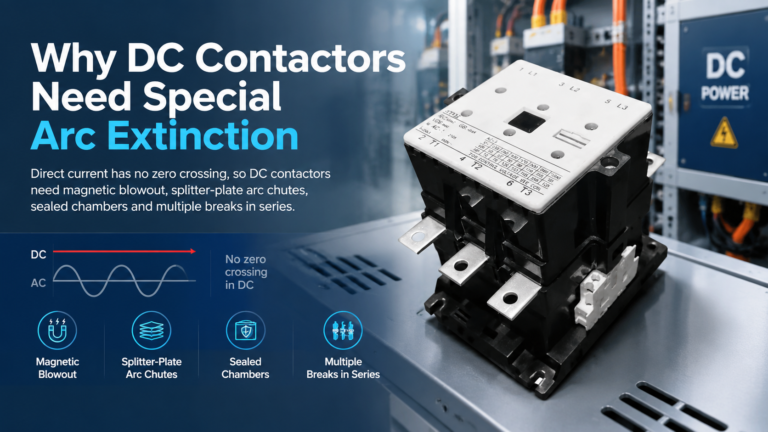
DC contactors need special arc extinction because DC current has no natural zero crossing. See how magnetic blowout, arc chutes and series breaks kill a DC arc — and how to specify one correctly.
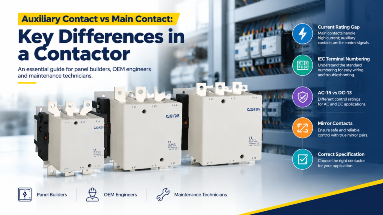
Main contacts carry the motor current; auxiliary contacts carry control signals. Learn the real rating gap, IEC terminal codes, and how to spec both correctly.
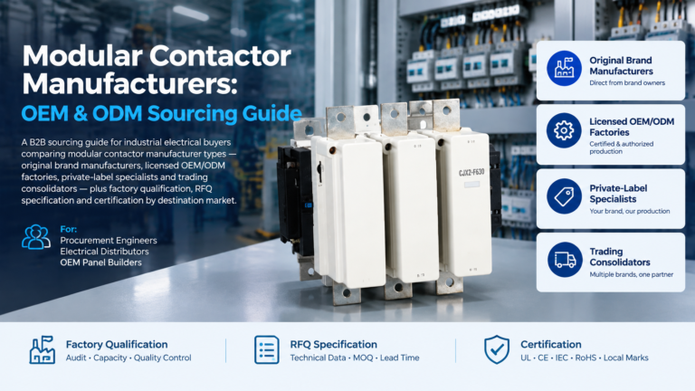
A sourcing guide to modular contactor manufacturers: match the four supplier archetypes, qualify any factory with a nine-point framework, and send an RFQ that gets comparable quotations.