AC Contactor Market: Standards, Segments and Sourcing Regions
A structural map of the AC contactor market: the IEC, UL and NEMA standards worlds, four demand segments, and what each sourcing region is actually good at.
Read More
Most three-phase motor starters are built from two devices working as a pair: a contactor that switches the motor on and off, and a thermal overload relay that protects it while it runs. If you are choosing an AC contactor for a new starter, or replacing the one in a burnt panel, the selection comes down to a few numbers on the motor nameplate, not a guess from the motor frame size. The short answer: pick a contactor whose AC-3 current rating is at least equal to the motor’s full-load current (FLC), then pair it with an overload relay whose adjustable range covers that same current and set the dial to the nameplate value. This guide walks through the sizing steps, a practical rating table, and the mistakes that cause starters to fail early.
A motor starter is the assembly that starts, stops, and protects a motor. In the most common arrangement, a direct-on-line (DOL) starter, a single contactor connects the motor straight to the supply when its coil is energised, and the overload relay sits between the contactor output and the motor to watch the current flowing to it.
So when someone says “contactor for a motor starter”, they usually mean the main switching device inside a DOL, reversing, or star-delta starter — sized for motor duty, not for general switching.
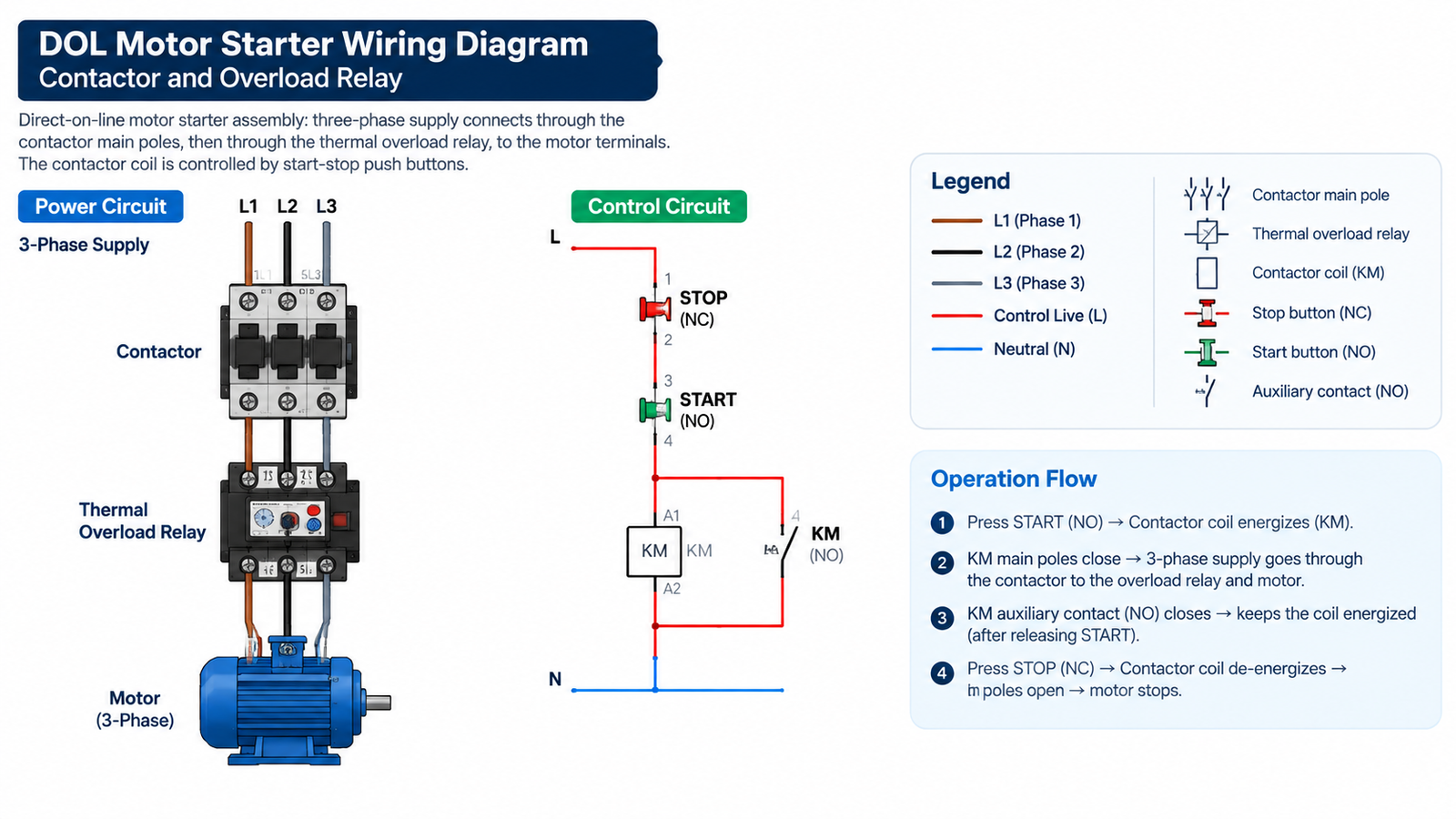
This boundary is where many starter faults start. A contactor is designed to make and break the circuit under defined conditions — for motor duty, it must close against the motor’s starting inrush current (typically six to eight times FLC for a short time) and break the running current when the motor is switched off. It is not designed to interrupt a sustained overload, and its contacts will erode quickly if they are forced to do so.
The thermal overload relay exists precisely because of that. It lets normal starting current pass, but if the motor runs overloaded, loses a phase, or is mechanically stalled, the relay heats up and opens its NC contact in the control circuit, which drops the contactor coil and stops the motor. For the same reason, a circuit breaker that protects the wiring is not a substitute: breakers and fuses are sized for short-circuit currents, not for the moderate, long-lasting overloads that damage motor windings. If you want the full division of duties, our comparison of a contactor vs circuit breaker explains which device protects what.
Follow these steps in order. The complete logic behind each one is covered in our guide on how to size and select a contactor; here is the motor-starter version.
The table below gives typical values for three-phase motors at 400V, 50Hz. Currents are approximations for planning; always confirm against the actual motor nameplate before buying.
| Motor power (kW) | Typical FLC at 400V (A) | Minimum AC-3 contactor frame (A) |
|---|---|---|
| 1.5 | 3.4 | 9 |
| 2.2 | 4.8 | 9 |
| 4 | 8.2 | 12 |
| 5.5 | 11 | 18 |
| 7.5 | 15 | 18-25 |
| 11 | 21 | 25-32 |
| 15 | 28 | 32-40 |
| 18.5 | 34 | 40 |
| 22 | 41 | 50 |
| 30 | 57 | 65 |
| 37 | 70 | 80 |
| 45 | 84 | 95 |
| 55 | 103 | 115 |
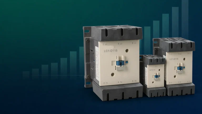
The same motor at 380V draws slightly more current, and at 415V slightly less, so re-check the current whenever the local supply differs from 400V. Large-frame motor-duty contactors such as the CJX2-F series cover the heavier end of this range with the AC-3 ratings printed for each frame.
The overload relay is chosen independently of the contactor frame, even though the two are mounted together and often supplied as a matched set. Its job is to protect the motor, so it is selected from the motor FLC, not from the contactor rating.
If you want to see how the relay and contactor behave together when something goes wrong, our contactor troubleshooting guide covers the symptoms that show up when either device is wrongly matched.

A reversing starter uses two contactors, one for each direction, because swapping any two supply phases reverses the motor. The danger is that if both contactors close at the same time, the phases are short-circuited through the two contactors. Two protections are standard: electrical interlocking through the auxiliary contacts, and mechanical interlocking, where a physical linkage prevents both armatures from closing even if the coils are energised together by a fault or a wiring error.
For this duty you need pairs of contactors built or supplied as interlocked units, such as the CJX2-F400 mechanical interlocking contactor, which is designed for reversing and changeover applications up to the heavier motor sizes. The mechanical interlock is the layer that keeps working when the control wiring does not.
A contactor for a motor starter is sized in three steps: read the motor FLC from the nameplate, choose a frame whose AC-3 rating covers that current, and pair it with an overload relay whose adjustable range brackets the FLC with the dial set to it. Get the coil voltage right for the control circuit, add mechanical interlocking for reversing duty, and the starter will switch reliably for years. When you are ready to spec the hardware, browse the CJX2-F series AC contactors and compare AC-3 ratings across the frames for your motor size.
Choose a contactor whose AC-3 current rating is at least equal to the motor’s full-load current. For example, a 7.5kW motor at 400V drawing about 15A typically needs an 18-25A AC-3 frame. Verify the FLC on the motor nameplate first.
No. A contactor is a switching device, not a protective device. Overload protection must come from a separate thermal or electronic overload relay that trips the contactor’s control circuit when the motor current stays too high.
A contactor is a single switching device. A motor starter is the assembly that switches and protects the motor, typically a contactor plus an overload relay, and often an enclosure and control devices.
Yes. The breaker is sized for short-circuit protection and does not detect the moderate, sustained overloads that damage motor windings. A correctly set overload relay is the device that protects the motor itself.
AC-3 is the IEC utilization category for starting squirrel-cage motors and switching them off at running speed. A contactor’s AC-3 current rating is the value to use when selecting it for normal motor starter duty.
Set the current dial to the motor nameplate full-load current, or within the allowance permitted by your local code (commonly up to about 115-125% depending on service factor). Never set it by the breaker size or the contactor rating.