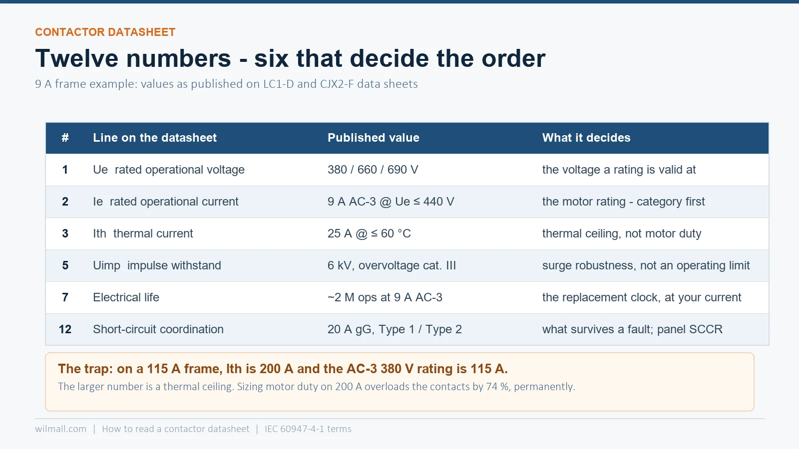
A contactor datasheet is not a list of equivalents — it is a set of twelve numbers that each answer a different question. The four that decide whether the device survives are Ie qualified by utilisation category (the motor rating), Ith with its ambient clause (the thermal ceiling), electrical life at your actual current (the replacement clock), and the coordination line (what happens under a short circuit). Most sourcing errors come from reading one number — usually Ie or the AC-3 kW — and treating the other eleven as decoration. On a 115 A frame, for example, Ith is 200 A: a 74 % higher number that says nothing about motor duty at all.
We are on the supplier side of this conversation, which means we see both halves of the problem. Buyers compare two datasheets by the AC-3 kW column and pick the cheaper one, then discover at commissioning that the coil holds at 20 % below nominal but not at 15 %, that the terminal will not take 16 mm², or that the promised 1 million operations were quoted at 25 % of the actual load.
This is a reading guide, in the order the numbers appear on a real sheet, with worked values from our own CJX2-F series y LC1-D series data. Read it once and the next datasheet you open will look like a structured document instead of a wall of symbols.
The Twelve Numbers on One Page
| # | Line on the datasheet | Typical value, 9–38 A frame | What it really decides |
|---|---|---|---|
| 1 | Ue — rated operational voltage | 380 / 660 / 690 V (up to 1000 V on large frames) | Which supply the rating below is valid on |
| 2 | Ie — rated operational current, with category | 9 A AC-3 at Ue ≤ 440 V; 25 A AC-1 | The motor-switching capability — the number you size on |
| 3 | Ith — conventional free-air thermal current | 20–25 A at ≤ 60 °C for a 9 A frame; 200 A on a 115 A frame | Thermal ceiling for non-motor duty; never the motor rating |
| 4 | Ui — rated insulation voltage | 690 V (IEC) / 600 V (UL) | Clearance and creepage design; the ceiling for Ue |
| 5 | Uimp — rated impulse withstand voltage | 6 kV (8 kV on larger frames) | Surge immunity; matters on VFD-fed and exposed systems |
| 6 | AC-3 power — kW, or hp in North America | 4 kW at 400 V; 5 hp at 480 V | Cross-brand comparison; the customer’s language |
| 7 | Electrical life at rated current | ~2 million operations at 9 A AC-3 | When the contact tips are worn out |
| 8 | Mechanical life | ~15 million operations | When the mechanism is worn out |
| 9 | Max. operating rate | 3600 operations/hour at 60 °C | Whether your duty cycle is legal at all |
| 10 | Coil — voltage, inrush VA, sealed VA, limits | 70 VA closing / 8 VA sealed at 220 V; 85–110 % pickup | Control transformer, PLC output, holding loss |
| 11 | Terminals — capacity and torque | 1–4 mm² (AWG 18–10), 1.7 N·m, 75 °C Cu | Whether the installer can land the cable properly |
| 12 | Short-circuit coordination | 20 A gG at ≤ 690 V, Type 1 or Type 2 | What survives a fault, and the panel’s SCCR |
Numbers 1–2: Ue and Ie Are Always a Pair
A current rating without a voltage and a utilisation category is not a rating. IEC 60947-4-1 defines Ie at Ue in a category, which is why a single device carries several current figures that differ by a factor of two or more.
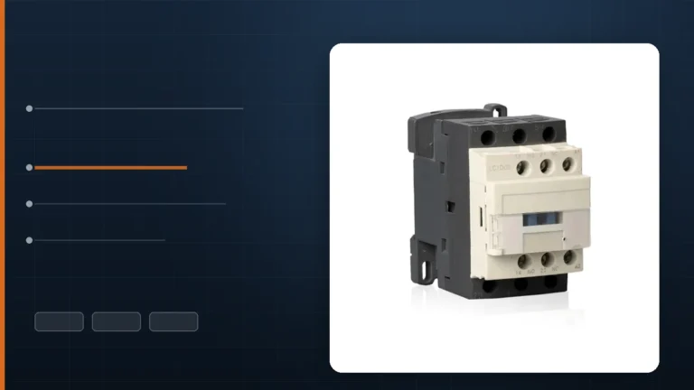
Take the LC1-D09 from our catalogue: 9 A at AC-3, Ue ≤ 440 V, and 20 A thermal. The same 9 A frame publishes 4 kW at 380 V, but only if the load is a squirrel-cage motor started and stopped at full speed. Put the same contacts on a resistive heater and the AC-1 figure applies; put them on plugging or inching duty and the AC-4 figure applies, which is a fraction of the AC-3 number.
Practical rule: find the category first, then the voltage, then the current. If a datasheet gives one current figure with no category, treat it as AC-1 and discount it heavily for motor duty. For the category definitions themselves, see our AC-1 to AC-4 guide and the AC-3 rating chart.
Number 3: Ith — the Biggest Number, the Least Useful
Ith is the conventional free-air thermal current: the current the device can carry in eight-hour duty, in free air, at the ambient stated in the footnote, without exceeding the temperature-rise limits. It is a thermal rating, not a switching rating.
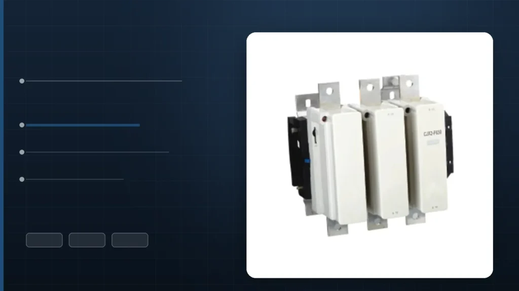
On our CJX2-F115 the two numbers sit next to each other and could not be more different: Ith 200 A, AC-3 380 V rating 115 A. The 200 A figure is 74 % higher, and it is the figure that ends up in a quotation when someone is in a hurry. Sizing a 132 A motor on a 200 A Ith rating is a warranty claim waiting to happen.
Two footnotes matter more than the number:
- The ambient clause. “Ith at ≤ 60 °C” and “Ith at ≤ 40 °C” are different products. A panel in a tropical plant room runs well above 40 °C internal, which is why the derating table — not the headline number — is the real specification. We covered the correction factors in contactor derating for temperature, altitude and dust.
- The signalling circuit has its own Ith. Auxiliary contacts are usually rated 10 A thermal with a much lower switching capability — the pilot-duty designator matters more than the 10 A.
Numbers 4–5: Ui and Uimp Describe Insulation, Not Operation
These two are consistently misread as “maximum voltage”, and they are not.
| Symbol | Meaning | Typical value | What it constrains |
|---|---|---|---|
| Ui | Rated insulation voltage — the voltage on which clearance and creepage distances are based | 690 V (IEC), 600 V (UL/CSA) | The highest Ue you may ever assign to the device |
| Uimp | Rated impulse withstand voltage — a 1.2/50 µs test wave the insulation survives | 6 kV at 690 V system voltage, overvoltage category III | Transient robustness: switching surges, lightning-induced waves, VFD switching |
The 6 kV figure is not a marketing number; it follows from the system voltage and the overvoltage category in the installation. A 690 V system in overvoltage category III implies 6 kV impulse withstand; a 400 V system in the same category implies 4 kV. If a datasheet quotes Uimp without stating the overvoltage category and pollution degree, the number cannot be checked — and on a VFD output or a long motor feeder, that is exactly the parameter that explains mysterious insulation failures.
Our large frames go further: the CJX2-F series is published at Ui 1000 V with Ue 380 / 660 / 1000 V. That is a deliberate design statement for 690 V and 1000 V mining and marine systems, not a suggestion that the device should be run at 1000 V on a 400 V panel.
Number 6: AC-3 Power — the Only Fair Cross-Brand Comparison
Ampere ratings are not comparable across brands, because different manufacturers use slightly different frame boundaries. The AC-3 kW figure at a stated voltage is comparable, because it is derived from the same standardised motor current table.
Two examples from our own range make the point:
| Device | AC-3 at 230 V | AC-3 at 380–400 V | AC-3 at 660 V | Ith |
|---|---|---|---|---|
| LC1-D09 (9 A) | 2.2 kW | 4.0 kW | 5.5 kW | 20 A |
| LC1-D12 (12 A) | — | 5.5 kW | — | 20 A |
| LC1-D18 (18 A) | — | 7.5 kW | — | 32 A |
| LC1-D25 (25 A) | — | 11.0 kW | — | 40 A |
| LC1-D32 (32 A) | — | 15.0 kW | — | 50 A |
| LC1-D40 (40 A) | — | 18.5 kW | — | 60 A |
Notice how the kW column rises faster than the ampere column: 9 A gives 4 kW, 32 A gives 15 kW. That is not a misprint — the kW figure is a motor rating at a nominal voltage, and the current for a given kW falls as the voltage rises. A 15 kW 400 V motor draws about 28 A, so a 32 A frame is correct with margin.
If the customer speaks horsepower, convert once and be explicit about the voltage, because 5 hp exists at 480 V and at 575 V with different currents. Our article on UL 508 vs IEC 60947-4-1 covers the mapping and the code basis (NEC 430.83).
Numbers 7–8: Two Clocks, and Only One of Them Matters
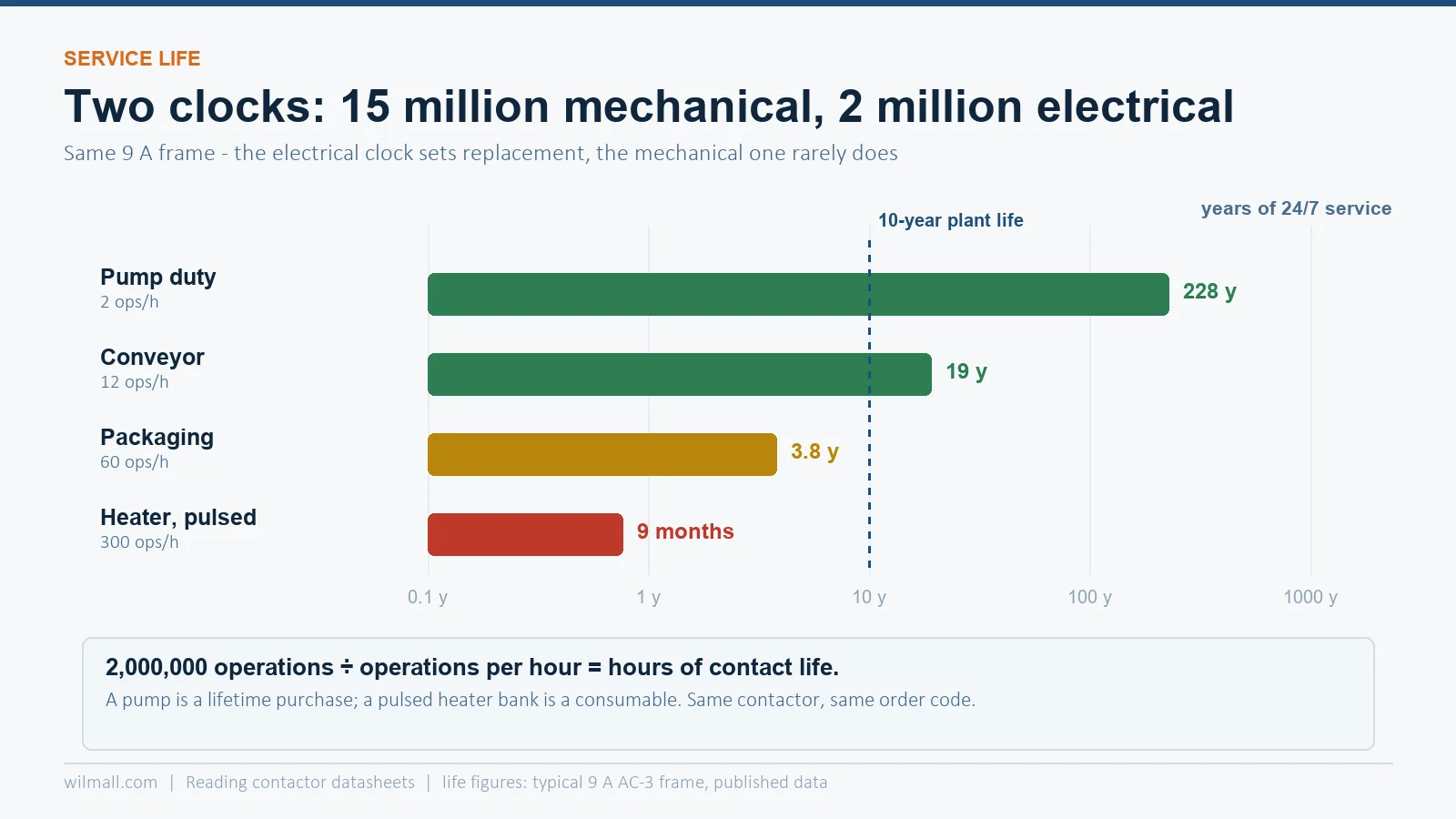
Every datasheet publishes two lives. They measure different wear mechanisms and they differ by roughly an order of magnitude.
- Mechanical life — operations with the coil energised but no current in the main poles. It measures the mechanism: armature, springs, latch, bearings. A 9 A frame typically publishes 15 million operations.
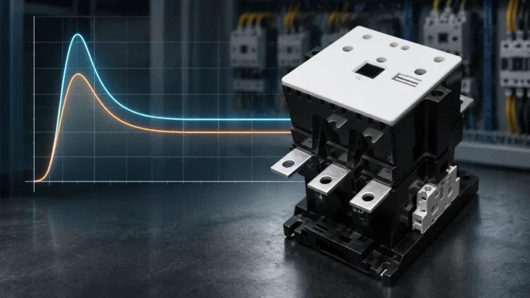
- Electrical life — operations while breaking actual current. It measures contact erosion, which is driven by arc energy, not by the mechanism. The same frame publishes roughly 2 million operations at 9 A AC-3 — and only 0.6 million at 25 A AC-1, where the arc lasts longer.
The electrical figure is the one to plan maintenance on, and it must be read at your current, not at the frame’s headline rating. Life curves published in catalogues fall steeply with current; a device at 80 % of its AC-4 rating can lose 90 % of its operations.
Convert the figure to a service interval before you quote, because that is what the customer will do:
| Duty | Operations per hour | Electrical life at 2 million | Years, 24/7 |
|---|---|---|---|
| Pump, occasional start/stop | 2 | 2,000,000 h | ~228 years |
| Conveyor, cyclic | 12 | 166,700 h | ~19 years |
| Packaging machine | 60 | 33,300 h | ~3.8 years |
| Heater bank, pulsed control | 300 | 6,670 h | ~9 months |
That table explains why the same contactor is a lifetime purchase on one machine and a consumable on another. It is also why “1 million operations” on a quotation means nothing until the current and the duty are stated. For the full set of duty limits, see contactor duty cycle and operating frequency.
Number 9: Maximum Operating Rate — the Constraint Nobody Checks
Electrical life tells you how many operations the device will survive. Maximum operating rate tells you how fast it may be asked to perform them. A 9 A frame publishes 3600 operations per hour at 60 °C; large frames fall to 1200 per hour or lower.
The two are independent. A device rated 2 million operations and 3600 per hour is not a device for 600 operations per minute in a hot panel — the thermal limit binds first, and the failure mode is coil overheating and contact welding rather than gentle wear. If your application pulses a heater or jogs a hoist, check this line before the current line.
Numbers 10–11: Coil Data and Terminals
The coil section deserves its own article — we wrote one on coil inrush VA, sealed VA and voltage tolerance — but four lines are enough to check a quote:
- Voltage and frequency. A 220 V 50 Hz coil on a 60 Hz supply draws less current and holds with less force. If the customer’s control supply is 60 Hz, order the 60 Hz coil.
- Inrush VA vs sealed VA. Typically 6–15× apart. Inrush sizes the control transformer and the PLC output; sealed sizes the panel heat load.
- Pickup and drop-out limits. IEC 60947-4-1 requires closing between 85 % and 110 % of Us, and release between 20 % and 75 % (AC). Our catalogue states the same window: close 85–110 % Us, open 20–75 % Us.
- Coil loss in watts. This is the continuous heat injected into the enclosure. Ten energised coils is a small heater running non-stop.
On terminals, three numbers decide whether the installation passes inspection: the conductor range (1–4 mm², AWG 18–10 on the 9 A frame), the conductor temperature rating (75 °C copper in North America), and the tightening torque (1.7 N·m / 15 lb-in). A high-power circuit landed on a 4 mm² terminal is a fire risk, and a loose terminal is the most common cause of contactor overheating that is blamed on the contactor. Terminal identification — A1/A2, 13/14, 95/96 — is covered in terminal numbering across IEC, NEMA and UL.
Number 12: Short-Circuit Coordination — the Missing Line
The most frequently absent line on a Chinese or Indian datasheet is the coordination table: which short-circuit protective device has been tested with this contactor, at which prospective current, and whether the combination achieves Type 1 or Type 2.
The definitions are short and worth knowing by heart:
- Type 1 — after the fault, no danger to people or installation, but the contactor and/or overload may be damaged and need replacement.
- Type 2 — no damage except light contact welding that is easily separated; the starter is suitable for further use after inspection.
For a 9 A frame, a 20 A gG fuse at ≤ 690 V is a typical pairing; the exact combination, the prospective current and the coordination type belong on the datasheet, not in a sales e-mail. Without that line, a panel builder in a UL 508A workshop cannot establish the panel’s SCCR, and the whole quotation stalls.
Reading a Real Row: CJX2-F115
Here is how the numbers look when they belong to an actual product line. Our CJX2-F series publishes the following, and the reading order is the practical part.
| Line | Published value | How to read it |
|---|---|---|
| Poles | 3P / 4P | 4-pole for neutral switching or two-circuit control |
| Rated operational voltage Ue | 380 / 660 / 1000 V | Three rating families on one device; pick the one matching the supply |
| Rated insulation voltage Ui | 1000 V | Insulation designed for 1000 V systems — the highest Ue it may carry |
| Control supply Us | 48, 110, 220, 380, 440/600 V AC | Coil options; check the customer’s control voltage before quoting |
| Pickup / drop-out | 85–110 % / 20–75 % of Us | The IEC window for reliable closing and guaranteed release |
| Thermal current Ith | 200 A (F115); 315 A (F265); 800 A (F630) | Thermal ceiling only — do not size a motor on it |
| AC-3 at 380 V | 115 A (F115); 265 A (F265); 630 A (F630) | The motor rating that matches the model number |
| AC-3 at 660 V | published separately, lower than the 380 V figure | Same device, higher voltage, lower current — always read both columns |
Two things become visible only when the rows are read together. First, the model number encodes the AC-3 380 V rating, not the thermal rating — F115 is a 115 A motor contactor with a 200 A thermal ceiling. Second, the AC-3 figure at 660 V is lower than at 380 V on the same device, which is why a 690 V project cannot simply reuse a 400 V selection. If model-number decoding is your immediate problem, our guide to reading contactor model numbers and the cross-reference rules go deeper.
The Five-Line Check We Run Before Quoting
- Category and voltage first. Confirm AC-3 (or AC-1 for heaters, AC-4 for plugging) and the actual system voltage, then read the matching current.
- Ith is not the rating. Check it only for ambient derating and for non-motor loads.
- Life at the actual current. Multiply operations per hour by the expected service years and compare with the published electrical life curve.
- Coil pair and limits. Inrush VA for the control transformer, sealed VA for panel heat, and 85–110 % pickup for the supply quality.
- Coordination and certification. Fuse class, coordination type, and the certificate number — the three lines that make a panel approvable.
Preguntas frecuentes
What is the difference between Ie and Ith on a contactor?
Ie is the rated operational current for switching a defined load in a defined utilisation category at a defined voltage — the motor rating. Ith is the conventional free-air thermal current the device can carry continuously without exceeding its temperature-rise limits. On a 115 A frame, Ith is typically 200 A, which is why Ith must never be used to size motor duty.
Which number should I compare between two brands?
The AC-3 kW rating at the same voltage and the same utilisation category. Ampere ratings are not directly comparable because frame boundaries differ; the kW figure is derived from the standardised motor current table and is therefore a like-for-like comparison.
Why is electrical life so much shorter than mechanical life?
Mechanical life counts operations with no current in the main poles, so only the mechanism wears. Electrical life counts operations that break current, so the contacts erode by arc energy. A typical 9 A frame publishes about 15 million mechanical and 2 million electrical operations at AC-3 — and considerably fewer at AC-4 or at AC-1 with a long arc duration.
What does Uimp 6 kV mean in practice?
It is the impulse voltage the insulation withstands in a standard 1.2/50 µs test, consistent with a 690 V system in overvoltage category III. It is a statement about transient robustness — switching surges, VFD-induced spikes, lightning-induced waves — not about the voltage you may operate the contactor at.
Why is the short-circuit coordination line often missing?
Because it requires tested combinations of contactor, overload relay and specific protective device at defined prospective currents. Publishing a coordination table is expensive, so only manufacturers who have done the testing can state Type 1 or Type 2 at a given fault level. If the line is absent, treat the device as suitable for Type 1 at best and confirm with the manufacturer before quoting a UL 508A panel.