CT Polarity, P1/P2 and S1/S2: Marking, Wiring and Field Testing
Published: Author: Lisa
Every current transformer has a polarity, and getting it wrong is invisible on a single-circuit ammeter but catastrophic in differential protection, directional relays and revenue metering. The markings P1/P2 (primary) and S1/S2 (secondary) are not decoration — they tell you which direction current flows through the winding at every instant. This guide explains the dot convention behind those terminals, how to wire a CT correctly the first time, and how to verify polarity in the field with nothing more than a battery and an analog meter.
What CT Polarity Actually Means
CT polarity describes the relative direction of current in the primary and secondary windings at the same instant. By international convention (IEC 61869, and the same idea behind the ANSI “dot” convention):
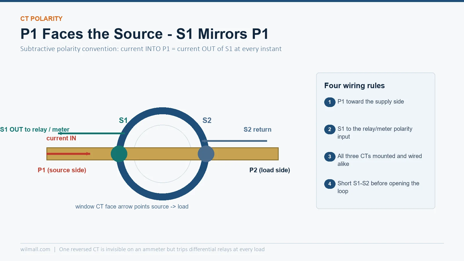
When instantaneous current flows into P1, it simultaneously flows out of S1 (into the external circuit through S1).
The convention is called subtractive polarity — it is the standard for practically every modern CT, so S1 always “mirrors” P1.
Think of P1/S1 as the “dot” ends of the two windings. The nameplate or the molded body marks them, typically P1 and P2 on the primary busbar path and S1/S2 on the secondary terminal block. Some small CTs print a dot or an arrow on the face instead — the arrow points in the direction of power flow, i.e. toward P2.
Why Polarity Matters
For a simple ammeter or thermal overload indication, a reversed CT reads the same RMS magnitude — nothing seems wrong. The problems appear the moment a circuit compares currents or cares about direction:
Differential protection: the relay subtracts currents entering and leaving the protected zone. One CT reversed makes the differential element see a permanent “fault”, and the trip is instant at every load step.
Directional and reverse-power relays: polarity (together with voltage transformer polarity) decides whether the relay sees forward or reverse power. A reversed CT makes a generator export relay guard in the wrong direction.
Revenue metering: energy meters integrate signed power. A reversed CT feeds negative real energy readings, and a mixed-polarity three-phase set loses part of the energy in vector cancellation — bills go wrong quietly.
Residual/earth-fault connection: in a residual connection of three CTs, one reversed CT produces a standing residual current that mimics an earth fault.
Wiring Rules: P1, P2, S1, S2
Follow four rules and most polarity problems never happen:
P1 faces the source. Mount the CT so that power flows from the source side through P1 toward P2. On window/bushing CTs the face label or arrow shows this direction; the primary “winding” is usually the cable itself.
Secondary wiring must mirror it. Connect S1 to the side of the relay or meter input that expects current arriving, and return from S2. Every device datasheet marks its CT input polarity — match S1/S2 to it consistently.
Keep the polarity consistent across all phases. All three CTs of a set must be mounted the same way and wired the same way. Mixed polarity inside one set is the classic cause of phantom residual current.
Never leave the secondary open. While the primary carries current, an open S1/S2 loop builds a dangerous voltage and can destroy the CT. Wire the shorting block first, then the meter, and only open the short with the circuit de-energised.
Solid and split-core window CTs such as the mini split-core current transformer for energy metering are the ones installers reverse most often, because on a window CT there is no visible primary terminal — the only polarity indicator is the printed arrow or H1/L1 marking on the housing. Check it before snapping the CT onto the cable, not after the meter reads backwards.
Field Test: The DC Flick (Battery) Method
When a CT has no markings left, or you need to prove the wiring before energising, the DC flick test verifies polarity in minutes with the circuit dead:
De-energise and isolate the primary circuit; disconnect the secondary from the relay/meter and connect an analog (moving-coil) milliammeter or a multimeter on a DC mA range across S1–S2, positive lead on S1.
Connect a 1.5–9 V battery through a push switch to the primary: positive to P1, negative to P2. On window CTs, route a few turns of test wire through the window instead — enough turns to get a readable deflection.
Close the switch and watch the needle at the moment of connection: a small positive kick (needle moves up-scale) means the assumed polarity is correct — current into P1 produces current out of S1.
Open the switch and watch again: the needle kicks the opposite way on break. That reverse kick is normal and confirms a healthy magnetic circuit.
Repeat per CT. Mark any CT that kicks down-scale, and swap its S1/S2 or rotate the CT 180° so the whole set agrees.
Use an analog meter or a meter with a peak-hold; a plain digital multimeter averages the flick and can show nothing useful. For final verification on protection cores, a proper CT from the DX-series line can be checked on a ratio/polarity test set, which superimposes the same principle at controlled amplitude.
Common Polarity Mistakes
Mounting window CTs backwards. Half of all polarity faults come from the physical orientation of a ring CT — the face arrow must point from source to load.
Trusting cable colour instead of terminals. What matters is the S1/S2 terminal of the CT and the polarity mark of the meter input, not which colour wire looks “positive”.
Testing with the secondary still connected to the relay. Other paths mask the flick; disconnect the measuring circuit first.
Forgetting PT polarity in directional schemes. Directional relays need both CT and VT polarity right; verify both, since either alone can reverse the torque.
Skipping the residual check. On a residual connection, measure the residual current at no load — anything but near-zero indicates a polarity or ratio mismatch inside the set.
Preguntas frecuentes
What is the difference between P1 and P2 on a current transformer?
They are the two ends of the primary path. P1 is the polarity end — instantaneous current entering P1 corresponds to secondary current leaving S1. Mount the CT with P1 toward the supply side.
What happens if a CT polarity is reversed?
Magnitude-only meters show no visible error, but differential relays trip at every load, directional relays guard the wrong way, and energy meters register negative or lost energy. The fault stays hidden until a comparison happens.
How do you test CT polarity with a battery?
Connect an analog DC milliammeter across S1/S2, apply a battery briefly across the primary with positive on P1, and watch for an up-scale kick on make. Up-scale on make confirms subtractive polarity; down-scale means the CT or wiring is reversed.
Is CT polarity the same for metering and protection CTs?
Yes — the P1/S1 convention is universal. The difference between metering and protection cores is accuracy class and saturation behaviour, not polarity.
Why does an open CT secondary create high voltage?
A CT is a series-connected current source. With no secondary path, the core drives the full flux swing into the magnetising branch and the secondary terminal voltage rises to dangerous levels. Always short S1/S2 before disconnecting a meter.
Current transformer accuracy classes decoded: 0.5 and 0.2S metering limits, 5P10 and 5P20 protection logic, burden effects and a class selection table.
CBCT-300 core balance current transformer for factories, suppliers, exporters, and distributors needing bulk purchase, custom OEM/ODM, and wholesale pricing.