


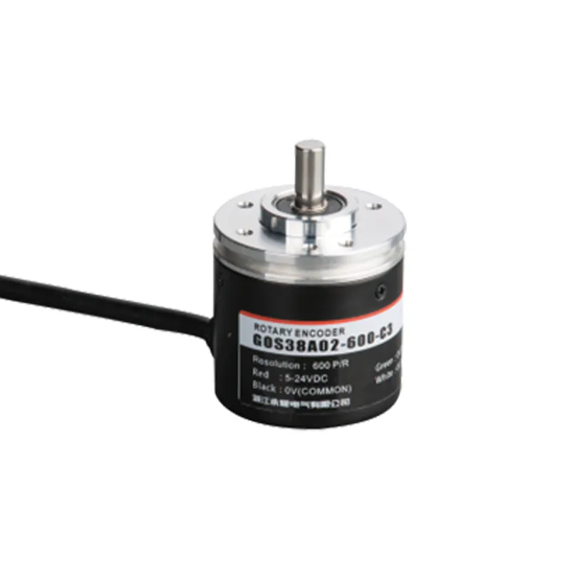
GOS38A02 Codificador rotatorio incremental con eje semihueco e IP65
The GOS38A02 incremental rotary encoder is designed for precision motion control in industrial automation applications. Featuring a compact 38mm diameter and semi-hollow shaft, it delivers accurate position and speed feedback with resolutions up to 10,000 pulses per revolution.
Interested in this product?
Please contact our sales team for the latest pricing, lead time, and technical consultation.
The GOS38A02 incremental rotary encoder is designed for precision motion control in industrial automation applications. Featuring a compact 38mm diameter and semi-hollow shaft, it delivers accurate position and speed feedback with resolutions up to 10,000 pulses per revolution. Its robust IP65-rated construction guarantees reliable performance in harsh environments. Compatible with various PLCs and control systems, the GOS38A02 offers versatile output signals including open collector, push-pull, and line driver, ensuring seamless integration in conveyor, robotics, CNC, and packaging machines.
Características principales
Incremental optical rotary encoder with high-resolution options from 100 to 10,000 PPR
Semi-hollow shaft design (typically 8mm diameter) for direct motor installation and easy coupling
IP65-rated housing protects against dust and water ingress for industrial durability
Wide DC input voltage range from 5 to 24V for flexible system compatibility
Multiple output signal types: open collector (NPN), complementary push-pull, and 5V line driver differential signals
Anti-interference circuitry for stable, noise-resistant signal output
Compact 38mm outer diameter facilitating integration in tight mechanical assemblies
Long cable options with protective rubber sleeves available
Ventajas del producto
High-resolution measurement enabling precise speed and position control
Semi-hollow shaft supports easier installation and shaft alignment
Robust IP65 protection increases encoder longevity in tough environments
Versatile outputs support a wide range of industrial control applications
Enhanced signal noise immunity ensures consistent feedback in electrically noisy settings
Space-saving compact size suits applications with limited installation room
Modelo de producto y significado
| G | 0 | S | 38 | □ | A | 02 | 2000 | C | 3 | 2M | |||
| Categoría producto | Tipo de producto | Forma de eje principal | Contorno de producto | Tamaño del eje principal, orificio del eje | Salida y formulario de sellado | Esquema estructura | Resolución | Formulario de salida | Señal de salida | Cable | |||
| G:incremental tipo | 0:megneto- electricidad | S:eje macizo | 38:φ38mm | □:φ6mm | A:goma de salida lateral | 02:2outline estructura2 | 10,20,50,60, 100,200,360, 400,500,600, 800,1000, 1024,1200, 2000,2048, 2500,3000, 3600,5000 | C:salida de colector abierto F:salida complementaria T:salida push pull L:Salida de 5 V A:Salida de 24 V | 1:fase Asignal 2:señal de fase AB 3:fase Señal ABZ 4:fase Señal ABA/B/ 5:fase ABZA/B/Z/ señal | Por defecto 2m línea,Para non 2m, etiquetado es suficiente |
Wiring table
| Color de la línea | Señal de salida C/F | – | Color de la línea | Señal de salida |
| marrón | VCC | marrón | VCC | |
| azul | GND | |||
| azul | GND | |||
| negro | Una fase | |||
| negro | Una fase | blanco | Fase B | |
| naranja | Fase Z | |||
| blanco | Fase B | |||
| negro rojo | Aphase | |||
| naranja | Fase Z | blanco rojo | Bphase | |
| rojo anaranjado | Fase Z | |||
| escudo | F -G | |||
| escudo | F -G |
Diferencia de fase de salida
salida complementaria/colector NPN salida en circuito abierto/salida push pull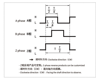
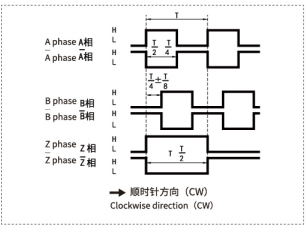
salida long line drive
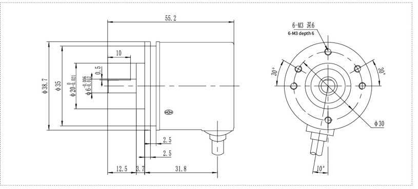
Dibujos mecánicos(mm)
Escenarios de aplicación
Industrial motor speed and position measurement for automation
CNC machinery for precision tool positioning and rotation feedback
Conveyor belt speed and position control in packaging lines
Robotics requiring accurate joint and axis feedback
Printing machines for synchronizing roller and sheet movements
Automated assembly lines demanding high reliability rotary feedback
Instalación y mantenimiento
Verify shaft diameter and match with the semi-hollow 8mm encoder shaft for secure fitting.
Align shafts carefully to prevent mechanical stress and ensure accurate feedback. Flexible coupling is recommended.
Secure the encoder firmly with mounting screws to prevent vibrations or rotational movement.
Connect the power supply between 5 to 24V DC, and wire output signals according to required interface (refer to wiring diagrams).
Use shielded, twisted-pair cables wherever possible to minimize electromagnetic interference.
Keep the encoder housing clean and free of dust buildup.
Periodically inspect electrical connections for tightness and signs of wear.
Replace the encoder promptly if signal integrity degrades or mechanical damage occurs.