


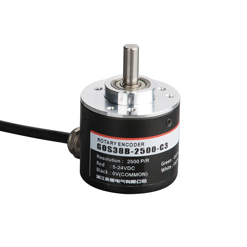
GOS38B Codificador rotativo incremental industrial con salida multirresolución
El encóder rotativo incremental GOS38B ofrece información de posición y velocidad fiable y precisa para una amplia gama de aplicaciones de automatización industrial. Diseñado con una robusta carcasa de 38 mm de diámetro y un sólido eje de 6 mm, este encóder ofrece varias resoluciones de pulsos adaptadas a los distintos requisitos de control.
Interested in this product?
Please contact our sales team for the latest pricing, lead time, and technical consultation.
El encóder rotativo incremental GOS38B ofrece información de posición y velocidad fiable y precisa para una amplia gama de aplicaciones de automatización industrial. Diseñado con una robusta carcasa de 38 mm de diámetro y un sólido eje de 6 mm, este encóder ofrece múltiples resoluciones de pulsos adaptadas a los distintos requisitos de control. Su avanzado circuito antiinterferencias y su robusto diseño garantizan un rendimiento estable en entornos difíciles, por lo que resulta ideal para motores, cintas transportadoras, maquinaria de envasado y sistemas CNC. El GOS38B es compatible con múltiples sistemas de control y proporciona una salida de señal coherente para optimizar la eficacia y precisión de la máquina.
Características principales
Codificador rotatorio incremental con resoluciones de impulsos de 100 a 5000 PPR (impulsos por revolución)
Diámetro compacto de 38 mm con eje macizo de 6 mm para una instalación versátil
Múltiples tipos de salida: colector abierto (NPN), contrafase y salidas complementarias
Robusto circuito antiinterferencias para una transmisión de la señal estable y resistente al ruido
Amplio rango de tensión de funcionamiento (normalmente 5-24 V CC) adecuado para la mayoría de los sistemas de control industrial
Gran durabilidad mecánica y carcasa con clasificación IP resistente al polvo y al agua
Compatible con varios PLC de automatización y reguladores de velocidad
Longitudes de cable y configuraciones de salida opcionales para personalizar las instalaciones
Ventajas del producto
La alta precisión y resolución mejoran la exactitud del control de posición y velocidad
Diseño duradero y compacto que resiste los entornos industriales más exigentes
Las señales de salida flexibles permiten la integración con diversos sistemas de control
El avanzado diseño antiinterferencias reduce el ruido de la señal y mejora la fiabilidad
Su fácil instalación reduce el tiempo de inactividad y los esfuerzos de mantenimiento
Admite una amplia gama de maquinaria industrial y necesidades de automatización
Modelo de producto y significado
| G | 0 | S | 38 | B | 2500 | C | 3 | 2M | ||||
| Categoría producto | Tipo de producto | Forma de eje principal | Contorno de producto | Tamaño del eje principal, orificio del eje | Salida y formulario de sellado | Resolución | Formulario de salida | Señal de salida | Cable | |||
| G:tipo incremental | O:megneto- electricidad P:fotoelec- tricidad | S: eje macizo | 38:φ38mm | □:φ6mm 08:φ8mm | B: salida lateral metálica D:salida trasera metálica | 10,20,50, 60,100, 200,360, 400,500, 600,800, 1000,1024,1200,200,2048,2500,3000,3600,5000
| M:salida de cantidad analógica C:salida de colector abierto F:salida complementaria T:push pulloutput L:Salida de 5 V A:Salida de 24 V | 1:señal de fase A 2:señal de fase AB 3:fase Señal ABZ 4:Señal ABA/B 5: señal de fase ABZA/B/Z/ 6:420mA 7:0-5V 8:0-10V | 2Defecto 2m línea,Para non 2m, etiquetado es suficiente | |||
Tabla de cableado
| Color de la línea | Señal de salida C/F/T | Color de la línea | Señal de salida L/A | Color de la línea | M señal(corriente) | Color de la línea | Señal M (tensión) | |||
| rojo | Vcc | rojo | Vcc | Marrón | Vcc | Marrón | Vcc | |||
| negro | 0V | negro | 0V | blanco | 0V | blanco | 0V | |||
| verde | Aphase | verde | Aphase | verde | 1 | verde | +U | |||
| blanco | Fase B | blanco | Fase B | amarillo | -1 | amarillo | -U | |||
| amarillo | Fase Z | amarillo | Zphase | escudo | F -G | escudo | F -G | |||
| escudo | F -G | marrón | A/ fase | |||||||
| gris | B/fase | |||||||||
| naranja | Z/fase | |||||||||
| escudo | F -G |
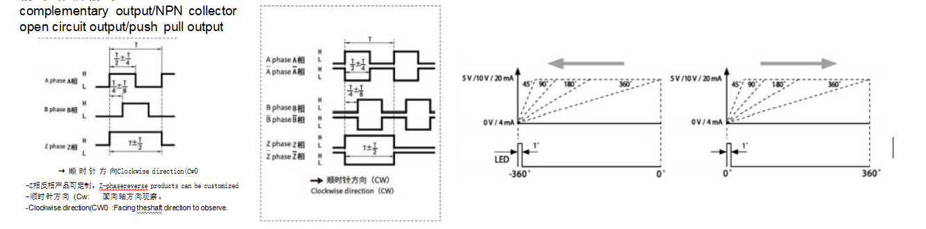
Diferencia de fase de salida
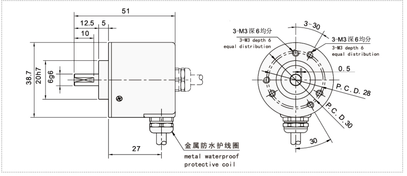
Dibujos mecánicos(mm)
Escenarios de aplicación
Velocidad del motor e información de posición en la automatización industrial
Supervisión y control de la velocidad de las cintas transportadoras
Sincronización y funcionamiento de la maquinaria de envasado
Detección de posición de equipos CNC
Robótica para el ángulo de articulación y retroalimentación rotacional
Maquinaria de impresión y automatización de cadenas de montaje
Instalación y mantenimiento
Asegúrese de que el eje del codificador coincide con el diámetro de acoplamiento de la aplicación (eje macizo de 6 mm).
Alinee con precisión el eje del codificador con el eje de la máquina; utilice acoplamientos elásticos para evitar tensiones de desalineación.
Monte firmemente el codificador con los herrajes suministrados para minimizar las vibraciones.
Conecte la fuente de alimentación dentro del rango de voltaje recomendado (5-24V DC) siguiendo el diagrama de cableado.
Utilice cables apantallados para el cableado de señales a fin de evitar interferencias electromagnéticas.
Realice una limpieza periódica para eliminar el polvo y los residuos; evite utilizar productos químicos agresivos o chorros de agua.
Compruebe periódicamente que el cableado y los conectores están bien conectados y que la señal es correcta.
Sustituya el codificador si aparecen signos de desgaste mecánico o señales inestables.