
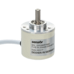

El encóder rotativo incremental de la serie 38 es un sensor compacto y muy fiable diseñado para proporcionar información precisa sobre la posición rotacional y la velocidad para automatización, máquinas CNC, robótica, envasado y otros equipos industriales. Gracias a la integración de tecnologías ópticas y mecánicas avanzadas, este encóder rotativo genera señales de impulsos incrementales precisas para garantizar la supervisión y el control de alta resolución del movimiento del eje. Su construcción duradera permite un funcionamiento estable en condiciones ambientales exigentes, lo que lo convierte en la opción ideal para la regulación de la velocidad, la medición de la posición y los sistemas de realimentación de bucle cerrado.
Características principales
Diseño compacto: Pequeño diámetro exterior de 38 mm con varias opciones de eje, incluidos ejes macizos y huecos, para mayor flexibilidad en la instalación.
Alta resolución: Disponible en varias opciones de impulsos por revolución (PPR), como 100, 200, 360, 400, 600 y resoluciones superiores de hasta 1024 PPR, para una realimentación angular y de velocidad precisa.
Múltiples tipos de salida: Admite los modos de salida de colector abierto, tensión y complementario para compatibilidad con diversos sistemas de control.
Amplio rango de tensión de funcionamiento: Funciona normalmente con CC de 5 a 24 V ±10%, adecuado para una amplia gama de entornos industriales.
Robusto y fiable: Construido con materiales duraderos, carcasa sellada (opciones IP65 o superior) y diseñado para soportar golpes, vibraciones y condiciones adversas.
Respuesta de alta frecuencia: Permite una medición precisa en tiempo real incluso a altas velocidades de rotación (hasta 6000 RPM o según se especifique).
Aplicaciones versátiles: Ideal para plegadoras, robótica, mecanizado CNC, equipos de envasado, procesamiento de alimentos y máquinas de corte solar.
Modelo de producto y significado
| 38 | □ | A | 05 | – | 1000 | – | T | 3 | – | 2M |
| Contorno de producto | Tamaño del principal eje, agujero del eje | Salida y formulario de sellado | Esquema estructura | Resolución | Formulario de salida | Señal de salida | Cable | |||
| 38:φ38mm | □:φ6mm (默认 | A:goma de salida lateral | 05:5 esquema estructura5 | 10,20,50, 60,100, 200,360, 400500, 600,800, 1000,1024, 1200,2000, 2048,2500, 3000,3600, 4096 | C: salida de colector abierto F:salida complementaria L:Salida de 5 V A:Salida de 24 V | 1:Señal de fase A 2:Señal de fase B señal fase AB 3:señal fase ABZ 4:fase Señal ABA/B/ 6:fase ABZA/B/Z/ señal | Por defecto 2m línea,Para non 2m, etiquetadoes suficiente |
Tabla de cableado
| Color de la línea | T señal de salida | – | Color de la línea | Señal de salida L/A |
| marrón | VCC | marrón | VCC | |
| azul | GND | |||
| azul | GND | |||
| negro | Una fase | |||
| negro | Una fase | blanco | Fase B | |
| naranja | Fase Z | |||
| blanco | Fase B | |||
| negro rojo | Aphase | |||
| naranja | Fase Z | blanco rojo | Bphase | |
| rojo anaranjado | Fase Z | |||
| escudo | F -G | |||
| escudo | F -G |
Ventajas del producto
Rendimiento estable y preciso: La tecnología de detección óptica del encóder, combinada con un mecanizado preciso, garantiza bajos índices de error y señales de salida uniformes para mejorar la precisión de la máquina.
Bajo consumo de energía: El diseño eficiente reduce el consumo de energía manteniendo una alta integridad de la señal.
Fácil integración: Las múltiples señales de salida (fases A, B, Z) y las interfaces estándar (TTL, HTL, ABZ) facilitan la conexión directa a diversos PLC, controladores de movimiento y microcontroladores.
Opciones de montaje flexibles: Admite modos de terminación de cables y conectores de entrada lateral con opciones para diferentes estilos de eje y bridas de montaje.
Durabilidad en condiciones extremas: Resistentes al polvo, la humedad y los esfuerzos mecánicos; algunos modelos ofrecen carcasas de doble sellado para entornos de lavado o exposición a productos químicos.
Diferencia de fase de salida
salida push pull

salida de palangre

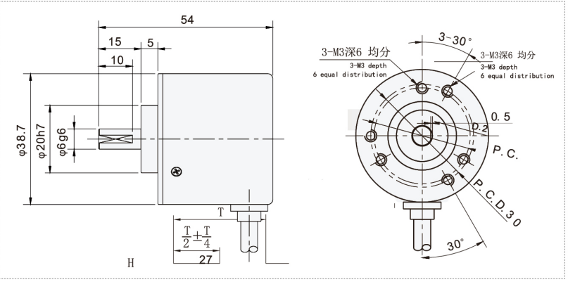
Dibujos mecánicos(mm)
Instalación y mantenimiento
Pasos de la instalación
Preparación: Asegúrese de que la máquina está apagada antes de la instalación. Verifique la compatibilidad con la tensión del sistema y los requisitos de la interfaz.
Montaje mecánico: Fije el codificador en el eje del motor o de la máquina utilizando abrazaderas o kits adaptadores adecuados. Asegúrese de que el eje esté alineado para evitar cargas radiales o axiales excesivas.
Conexión eléctrica: Conecte los cables o conectores de salida del codificador a las entradas del sistema de control, respetando el cableado correcto para el tipo de salida (por ejemplo, colector abierto, salida de tensión). Se recomienda utilizar cables apantallados para evitar ruidos en la señal.
Verificación: Encienda el sistema y compruebe los impulsos de salida con un osciloscopio o una entrada PLC para confirmar el correcto funcionamiento y la integridad de la señal.
Calibración: Si es necesario, realice la calibración de la posición cero o del pulso de referencia de acuerdo con el manual de su sistema de control.
Consejos de mantenimiento
Inspeccione periódicamente el montaje mecánico para comprobar si se ha aflojado o desgastado el eje.
Mantenga el codificador y los conectores limpios y secos; evite abrir la carcasa del codificador para evitar la contaminación.
Verifique la integridad del cable y la eficacia del apantallamiento anualmente o como parte del mantenimiento rutinario.
Evite realizar modificaciones eléctricas en los circuitos del codificador para mantener la garantía y el rendimiento.
Utilice fundas o botas protectoras en entornos difíciles para prolongar la vida útil.
Aplicaciones de los productos
El codificador rotativo incremental GLS38A05 se utiliza ampliamente en:
Sistemas de automatización industrial para realimentación de velocidad y posición de motores.
Robótica para el control de la posición de articulaciones y brazos.
Centros de mecanizado CNC para proporcionar datos precisos sobre la velocidad y la posición del husillo.
Sistemas de transporte y envasado para la regulación de la velocidad y el seguimiento de los productos.
Sincronización de maquinaria de impresión y textil.
Acerías y trenes de laminación para controlar la velocidad de los rodillos y la precisión del espesor.
Líneas de inspección y montaje automatizadas que requieren información de movimiento de alta resolución.
Solicite un presupuesto ahora
Nuestro equipo se pondrá en contacto con usted en un plazo de 24 horas.


