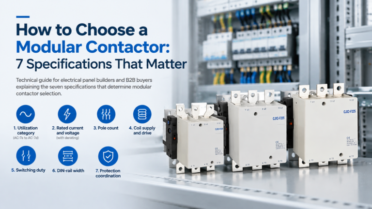
How to Choose a Modular Contactor: 7 Specifications That Matter
Seven specifications decide whether a modular contactor survives or fails: utilization category, current and derating, poles, coil supply, duty, rail space and protection.
Read More
Walk into any well-built control panel today and you will notice something: the block contactors that once dominated the back plate are gone. In their place, rows of slim devices snap onto a 35 mm rail, each one a self-contained switching cell. That is not a cosmetic change. Modular contactors have quietly become the structural layer of modern control systems — the point where controller logic finally becomes switched power.
This guide explains what “backbone” actually means in engineering terms: how the modular contactor fits into the control chain, why the 17.5 mm module grid reshaped panel design, where the IEC 61095 standard boundary sits, how to integrate coils with PLC and BMS outputs without creating leakage or thermal problems, and where a modular contactor is the wrong tool entirely.
Every automated system, from a hotel lighting board to a water-treatment skid, runs the same five-stage chain: sense → decide → interface → switch → load. Sensors and controllers get the attention, but the switching layer is where the system either works or fails in the field. The modular contactor occupies that layer.
Three properties are what make it structural rather than just another component:
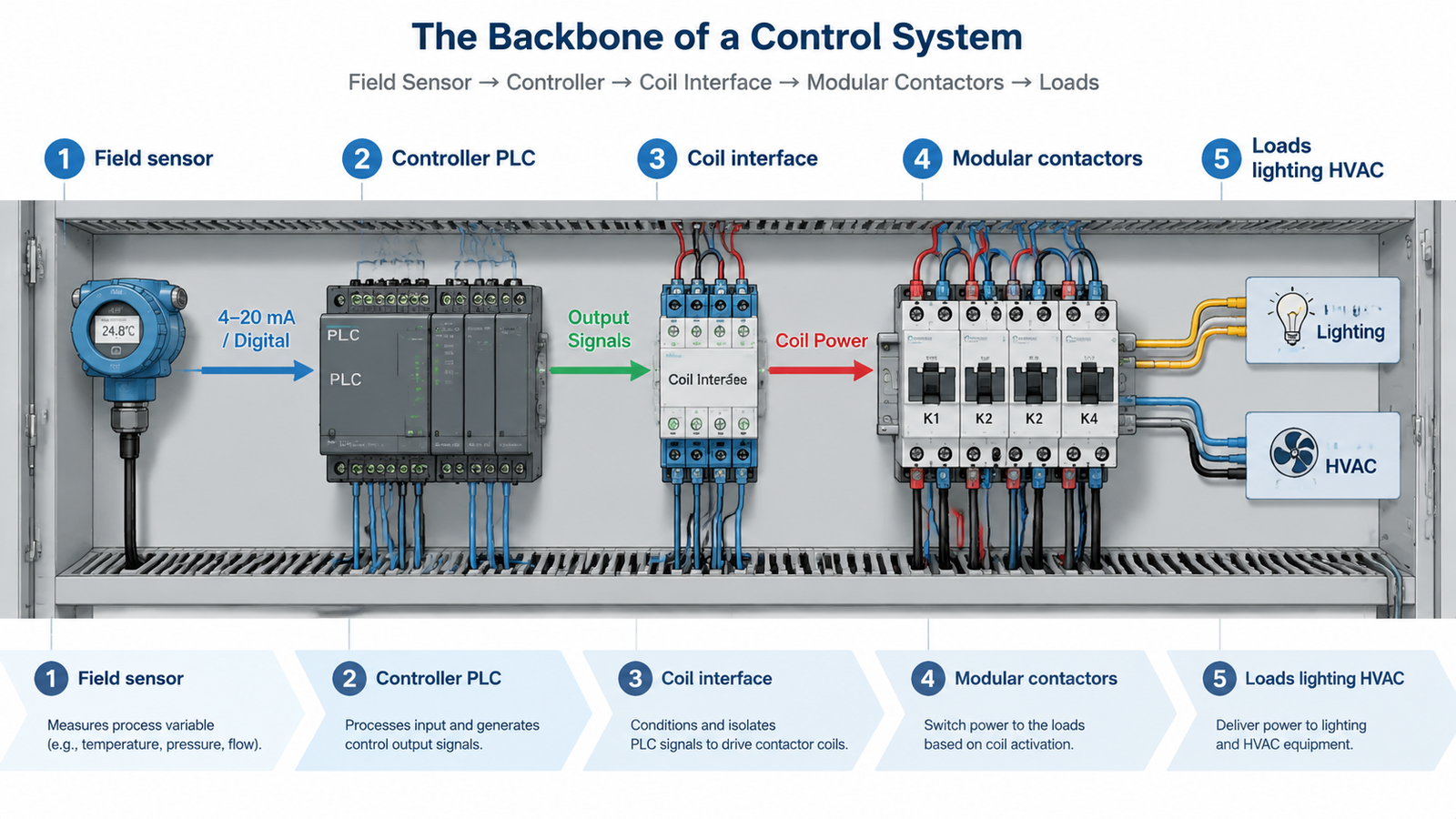
| Control-chain layer | Typical devices | What the modular contactor contributes |
|---|---|---|
| 1. Sense | Temperature, pressure, occupancy, float switches | — (consumes signals) |
| 2. Decide | PLC, BMS/BAS controller, timer, thermostat | — (issues commands) |
| 3. Interface | Interposing relays, coil terminals A1/A2, suppressors | Defines the coil voltage architecture of the whole panel |
| 4. Switch | Modular contactors (AC-7a/7b/7d duty) | Repetitive switching of lighting, heating, ventilation and auxiliary loads |
| 5. Load | Lighting zones, heaters, fans, pumps, small motors | Per-circuit isolation and status feedback via auxiliary contacts |
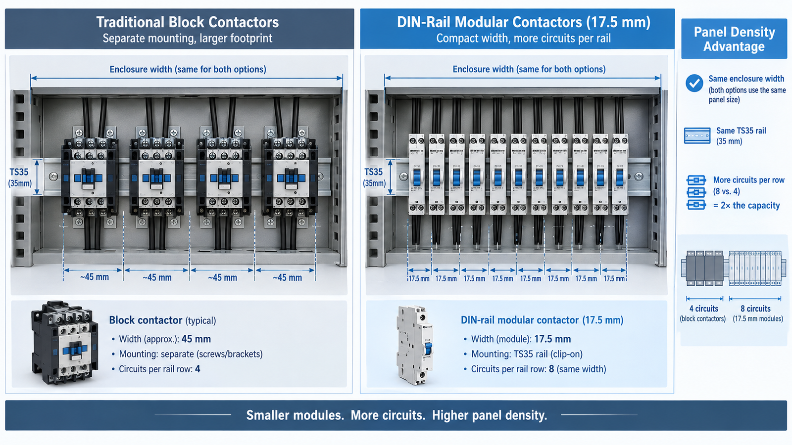
The 35 mm top-hat rail (TS35, standardized in IEC/EN 60715) is the physical foundation of the backbone. Devices clip on without drilling, and because every device width is a multiple of the 17.5 mm module, a panel builder can count capacity the way a warehouse counts shelf slots. A 1-metre rail run holds roughly 57 modules; a typical two-row compartment holds well over a hundred.
Compare that with the traditional approach. A block contactor for the same load class occupies 45 mm or more of width, needs its own mounting footprint, and leaves less room for wiring access between units. The difference compounds quickly across a panel.
| Rating class (AC-7a, 2P/4P) | Typical module width | Approx. units on a 1 m rail row |
|---|---|---|
| 16–25 A | 1 module (17.5 mm) | ~57 |
| 40–63 A | 2–3 modules (35–54 mm) | ~19–28 |
| 80–100 A | 3–4 modules (52.5–70 mm) | ~14–19 |
Widths vary by series and pole count — always confirm against the datasheet before freezing a panel layout.
Take a commercial floor with 24 lighting zones, each switching about 12 A of LED load under AC-7d duty. Using 25 A 2-pole modular contactors at one module each, the switching bank consumes 24 modules — about 420 mm of a single rail row — and the same row still accepts the upstream MCBs. The equivalent block-contactor layout would need roughly a metre of rail plus mounting hardware, and would almost certainly force a second enclosure or a deeper cabinet.
That arithmetic is the real reason modular contactors became the backbone: the switching layer stops being the thing that sizes the enclosure.
A backbone is only as good as its specification, and the most common specification error is treating modular contactors as “small industrial contactors.” They are not governed by the same standard, and the difference is not cosmetic.
Modular contactors for household and similar applications are certified to IEC 61095. Industrial contactors and motor starters fall under IEC 60947-4-1 and its AC-1 to AC-4 utilization categories. The 2023 revision of IEC 61095 (Edition 3.0) tightened the standard further, adding the AC-7d category for LED lighting loads, updated EMC immunity requirements and stricter marking rules — a direct response to smart-building and energy-management practice.
| Aspect | Modular contactor (IEC 61095) | Industrial contactor (IEC 60947-4-1) |
|---|---|---|
| Rated operational voltage | Typically ≤ 250–440 V AC | Up to 690 V AC and above |
| Utilization categories | AC-7a (cos φ 0.8), AC-7b (cos φ 0.45), AC-7d (LED) | AC-1, AC-3, AC-4 and others |
| Typical duty | Lighting, heating, ventilation, auxiliary circuits | Motor starting, machine loads, heavy duty |
| Mounting | DIN rail, modular grid | DIN rail or screw/panel mount |
| Short-circuit coordination | Conditional rating with declared fuse/MCB | Type 1 / Type 2 coordination tables |
The practical takeaway for specifiers: a 25 A modular contactor is not a 25 A AC-3 contactor. A typical modular unit rated 25 A under AC-7a may only carry 8.5 A under AC-7b motor duty — the same figure printed on the same housing. Read the category column, not just the amps.
This is where backbone design gets technical. The contactor’s coil is the load of the control system, and mismatched coil/output pairing is the single most common integration failure in modular panels.
Coil families. Standard options run from 24 V AC and 110/220–240 V AC coils to 12/24 V DC coils, universal 24–240 V AC/DC coils and low-consumption electronic coils (roughly 2–4 VA hold-in) for controller-driven designs. Coil power matters: a typical 25 A modular contactor draws in the region of 53 VA on pull-in and about 6.5 VA sealed — small, but not negligible when one output card drives a dozen of them.
The leakage trap. PLC triac and solid-state relay outputs leak 1–5 mA RMS even when OFF. A contactor coil usually needs 20–50 mA to seal in, so the leakage alone will not close it — but it will keep it closed. Modular contactor coils typically hold until the voltage falls to 0.2–0.75 × Uc, so a leaky output that maintains even 30 % of nominal voltage across the coil can prevent release. The symptoms are familiar: a contactor that stays on when the PLC says off, a faint hum on a de-energized coil, or an output point that never truly reads 0 V.
The fixes are standard practice: a loading (bleeder) resistor across the coil to sink the leakage, an RC snubber for dv/dt and commutation, and an MOV for larger inductive coils. DC coils should always get a flyback diode.
| Controller output | Recommended coil | Suppression | Watch-outs |
|---|---|---|---|
| PLC relay contact, 24 V DC | 24 V DC coil | Flyback diode across coil | Check PSU budget for total inrush of the bank |
| PLC triac point, 230 V AC | 220–240 V AC coil | Loading resistor + RC snubber | Leakage may hold coil in — verify drop-out |
| BMS / BAS digital output | Electronic or universal AC/DC coil | Per BMS manufacturer guidance | Low hold-in VA (2–4 VA) reduces card loading |
| Timer / thermostat direct | Match the timer’s contact rating | RC snubber or MOV | Confirm timer can break the coil inrush |
| Manual selector / hard-wired | Any standard coil | MOV for inductive break | Keep manual override out of the PLC loop if required by spec |
For the wiring detail behind A1/A2, main terminals and auxiliary contacts, see our step-by-step guide on how to wire a contactor.
Density is the backbone’s advantage — until it becomes a heat problem. Every contactor in the bank dissipates power: contact resistance in the poles plus coil losses. A 63 A 3-pole modular unit may dissipate around 8 W per pole; multiply across a dense row and the panel’s internal air temperature climbs fast.
Under IEC 61439-1, the assembly is verified against temperature-rise limits at a declared ambient — typically a 35 °C 24-hour average with a 40 °C maximum for indoor service — either by test or by a validated calculation method such as IEC/TR 60890. Three effects deserve attention in a modular-heavy design:
| Design lever | Typical effect | Design note |
|---|---|---|
| Grouping / spacing factor | 10–25 % continuous-current reduction when fully loaded side by side | Use the manufacturer’s tested arrangement, not an assumed factor |
| Enclosure IP rating | Sealed IP54/IP65 enclosures trap heat; open-bottom IP21 sheds it | Recheck circuit ratings whenever the IP class changes |
| Coil duty | Electronically controlled coils dissipate 2–4 VA vs 6.5 VA+ for AC coils | Worth specifying in 24-hour-operating buildings |
| Ventilation / forced air | 12–18 °C reduction in dense zones with fan assistance | Must not compromise the declared IP rating |
| Declared ambient | Each +10 °C above rating point shortens insulation life roughly by half | Declare the real panel-room temperature on the drawings |
Modular contactors anchor recurring, moderate-duty switching. They are the wrong choice where motor duty, high short-circuit energy or heavy cycling dominate. The table below is the boundary in practice.
| Application | Modular contactor fit | Why |
|---|---|---|
| Commercial lighting control (zoned, timed, BMS-driven) | Excellent — AC-7a/AC-7d | High circuit count, silent operation, per-zone isolation |
| HVAC: fan coils, electric heaters, dampers | Excellent | Repetitive switching matched to AC-7a duty |
| Pumps and water systems (float/level switch control) | Good — verify AC-7b rating | Small motor loads; derate 25 A → 8.5 A class |
| Retrofit of legacy distribution boards | Excellent | No drilling; modules drop into existing rail space |
| 3-phase motor starting, compressors, machine tools | Not suitable | AC-3/AC-4 duty belongs to IEC 60947-4-1 contactors with overload protection |
| High short-circuit feeder positions | Verify carefully | Only the declared conditional rating with the specified fuse/MCB applies |
The last two rows are where projects go wrong. A modular contactor is only the switching element; it is not a motor starter, and it carries no overload protection of its own. For anything motor-duty, step up to an IEC 60947-4-1 contactor with a coordinated overload relay — our guides on contactors for motor starters et how thermal overload relays work cover that side of the boundary, and the AC-1 to AC-4 utilization categories article explains the rating logic behind it.
Before releasing a modular-heavy design for manufacture, work through this system-level checklist. It deliberately asks about the system, not the individual device — the selection details are covered separately in our guide to choosing a modular contactor.
| # | Question | Design impact if ignored |
|---|---|---|
| 1 | What is the load census per circuit — category and inrush? | Wrong utilization category; early contact welding |
| 2 | Which controller commands the coils — relay, triac, BMS? | Leakage hold-in, hum, outputs that never release |
| 3 | One coil voltage family or mixed? | Spare-parts chaos and miswiring during maintenance |
| 4 | Total module count, including 20 % spare capacity? | Enclosure too small at first modification |
| 5 | Declared ambient and enclosure IP class? | Temperature-rise failure under IEC 61439 verification |
| 6 | Grouping derating applied to the densest row? | Chronic overheating in daily-cycled lighting panels |
| 7 | Conditional short-circuit rating with which protective device? | Unverified fault withstand at the feeder |
| 8 | Suppression strategy per output type (RC, MOV, diode)? | Damaged output cards and erratic logic |
| 9 | Silence requirement — hotel, office, residential? | AC-coil hum complaints in occupied spaces |
| 10 | Status feedback needed per circuit (auxiliary contacts)? | No remote confirmation for BMS alarming |
| 11 | Switching frequency — cyc/h over the duty cycle? | Mechanical life exhausted years early |
| 12 | Any circuit that is actually motor duty? | Modular unit applied beyond its standard — unsafe |
No. Both switch a load with a coil, but a modular contactor is a power-switching device rated in amps for AC-7 category duty, built to live in a distribution board; a control relay switches signals and small control loads. The distinction matters for ratings and standards — see our comparison of contactors vs control relays.
Only for very small motors, and only if the unit is rated AC-7b for that motor’s current. For anything beyond fractional-kilowatt duty, an IEC 60947-4-1 contactor with a coordinated overload relay is the correct device.
Almost always off-state leakage from a triac or solid-state output partially energizing the coil. Fit a loading resistor across the coil and an RC snubber across the output, then confirm the coil actually drops out with the output commanded OFF.
Mechanically, as many as the rail holds — the module grid exists for that. Thermally, follow the manufacturer’s grouping derating and the assembly’s IEC 61439 temperature-rise verification. A fully populated row of loaded contactors cannot be treated as a row of individually rated devices.
They need coordination. Modular contactors carry a conditional short-circuit rating that is only valid with the specific upstream gG fuse or MCB declared by the manufacturer. Select the protective device from that declaration, not from convenience.
Scope and duty. IEC 61095 covers contactors for household and similar applications — the modular DIN-rail format, AC-7a/7b/7d categories. IEC 60947-4-1 covers industrial contactors and motor starters with AC-1 to AC-4 categories, higher voltages and coordinated motor protection. They are complementary, not interchangeable.
Modular contactors earn the “backbone” label because they solve the three problems that define modern control panels: how to switch dozens of circuits in limited space, how to let any controller command any load through a standard coil interface, and how to keep the whole switching layer serviceable module by module. Design them inside their IEC 61095 boundary, budget for the heat they generate, and protect the controller outputs that drive them.
And when a circuit crosses into motor duty, respect the boundary. The 3TF series AC contactor covers AC-3 duty from 9 A to 475 A at 380/400 V with thermal overload relay coordination — the industrial counterpart to everything described above. For the full switching range, browse the AC contactor category, start from what a contactor is and how it works, or compare architectures in our breakdown of modular vs traditional AC contactors. As a manufacturer-side supplier, we support OEM panel builders with consistent series, datasheets and matched accessory sets — send us your circuit schedule and we will return a component list with the coordination already checked.