


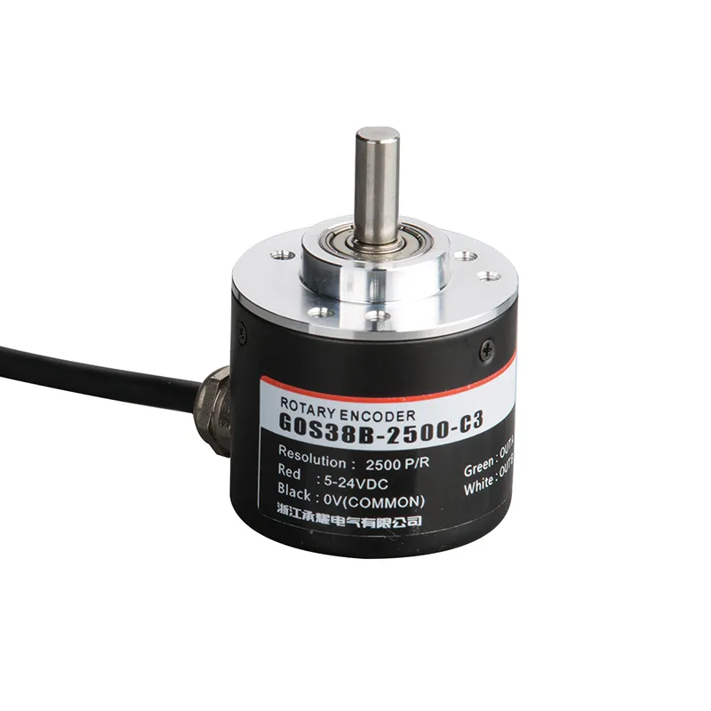
GOS38B Codeur rotatif incrémental industriel avec sortie multirésolution
Le codeur rotatif incrémental GOS38B offre un retour de position et de vitesse fiable et précis pour une large gamme d'applications d'automatisation industrielle. Doté d'un boîtier robuste de 38 mm de diamètre et d'un arbre solide de 6 mm, ce codeur offre plusieurs résolutions d'impulsions adaptées à des exigences de contrôle variées.
Interested in this product?
Please contact our sales team for the latest pricing, lead time, and technical consultation.
Le codeur rotatif incrémental GOS38B offre un retour de position et de vitesse fiable et précis pour une large gamme d'applications d'automatisation industrielle. Doté d'un boîtier robuste de 38 mm de diamètre et d'un arbre solide de 6 mm, ce codeur offre plusieurs résolutions d'impulsions adaptées à des exigences de contrôle variées. Son circuit antiparasite avancé et sa conception robuste garantissent des performances stables dans des environnements difficiles, ce qui le rend idéal pour les moteurs, les convoyeurs, les machines d'emballage et les systèmes CNC. Le GOS38B est compatible avec de nombreux systèmes de contrôle, fournissant un signal de sortie cohérent pour optimiser l'efficacité et la précision de la machine.
Caractéristiques principales
Codeur rotatif incrémental avec des résolutions d'impulsions allant de 100 à 5000 PPR (impulsions par tour)
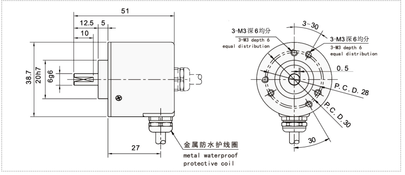
Diamètre compact de 38 mm avec un arbre solide de 6 mm pour une installation polyvalente
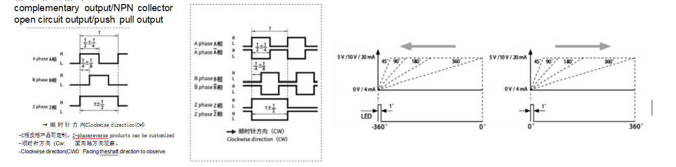
Plusieurs types de sorties : collecteur ouvert (NPN), push-pull et sorties complémentaires
Circuit antiparasite robuste pour une transmission de signaux stable et résistante au bruit
Large plage de tension de fonctionnement (typiquement 5-24V DC) convenant à la plupart des systèmes de contrôle industriels
Grande durabilité mécanique et boîtier classé IP pour la résistance à la poussière et à l'eau
Compatible avec divers automates et contrôleurs de vitesse
Longueurs de câble et configurations de sortie en option pour personnaliser les installations
Avantages du produit
La haute précision et la résolution améliorent la précision du contrôle de la position et de la vitesse.
Conception durable et compacte résistant aux environnements industriels difficiles
Les signaux de sortie flexibles permettent l'intégration avec différents systèmes de contrôle
La conception anti-interférence avancée réduit le bruit du signal et améliore la fiabilité.
L'installation facile réduit les temps d'arrêt et les efforts de maintenance
Prise en charge d'un large éventail de machines industrielles et de besoins en matière d'automatisation
Modèle de produit et signification
| G | 0 | S | 38 | B | 2500 | C | 3 | 2M | ||||
| Catégorie de produit | Type de produit | Forme de arbre principal | Contour de la produit | Taille de l'arbre principal, trou de l'arbre | Sortie et formulaire de scellement | Résolution | Formulaire de sortie | Signal de sortie | Câble | |||
| G:type incrémental | O:megneto- électricité P:photoelec- tricité | S : arbre plein | 38:φ38mm | □:φ6mm 08:φ8mm | B : sortie latérale en métal D : sortie arrière en métal | 10,20,50, 60,100, 200,360, 400,500, 600,800, 1000,1024,1200,200,2048,2500,3000,3600,5000
| M:sortie analogique de quantité C:sortie à collecteur ouvert F:sortie complémentaire T:push pulloutput L:Sortie d'entraînement 5V A:Sortie d'entraînement 24V | 1:signal de la phase A 2:signal de phase AB 3:phase signal ABZ 4:ABA/B/ signal 5 : phase ABZA/B/Z/ signal 6:420mA 7:0-5V 8:0-10V | 2Défaut 2m ligne, pour non 2m, L'étiquetage est suffisant | |||
Tableau de câblage
| Couleur de la ligne | Signal de sortie C/F/T | Couleur de la ligne | Signal de sortie L/A | Couleur de la ligne | Signal M (courant) | Couleur de la ligne | Signal M (tension) | |||
| rouge | Vcc | rouge | Vcc | Marron | Vcc | Marron | Vcc | |||
| noir | 0V | noir | 0V | blanc | 0V | blanc | 0V | |||
| vert | Aphase | vert | Aphase | vert | 1 | vert | +U | |||
| blanc | Phase B | blanc | Phase B | jaune | -1 | jaune | -U | |||
| jaune | Phase Z | jaune | Zphase | bouclier | F -G | bouclier | F -G | |||
| bouclier | F -G | brun | A/phase | |||||||
| gris | B/phase | |||||||||
| orange | Z/phase | |||||||||
| bouclier | F -G |
Différence de phase de la sortie
Dessins mécaniques (mm)
Scénarios d'application
Retour d'informations sur la vitesse et la position du moteur dans l'automatisation industrielle
Surveillance et contrôle de la vitesse des bandes transporteuses
Synchronisation et fonctionnement des machines d'emballage
Détection de la position de l'équipement CNC
Robotique pour le retour d'information sur l'angle et la rotation des articulations
Machines d'impression et automatisation des chaînes de montage
Installation et maintenance
Veillez à ce que l'arbre du codeur corresponde au diamètre de l'accouplement de l'application (arbre plein de 6 mm).
Aligner précisément l'arbre du codeur avec l'arbre de la machine ; utiliser des accouplements flexibles pour éviter les contraintes de désalignement.
Fixez solidement l'encodeur à l'aide du matériel fourni afin de minimiser les vibrations.
Brancher l'alimentation électrique dans la plage de tension recommandée (5-24V DC) en suivant le schéma de câblage.
Utilisez des câbles blindés pour le câblage des signaux afin d'éviter les interférences électromagnétiques.
Effectuez un nettoyage régulier pour éliminer la poussière et les débris ; évitez d'utiliser des produits chimiques agressifs ou des jets d'eau.
Vérifier périodiquement le câblage et les connecteurs pour s'assurer de la sécurité des connexions et de l'intégrité des signaux.
Remplacer le codeur s'il présente des signes d'usure mécanique ou des signaux instables.