


L'ultime tableau des tailles de presse-étoupe que vous devez utiliser aujourd'hui
10 Powerful Insights for Engineers: The Ultimate Cable gland size chart You Must Use Today
Choosing the correct cable gland size is crucial for safety, performance, and longevity across industrial installations. This article provides an authoritative Cable gland size chart and practical guidance for matching threads, diameters, and applications.
Introduction to Cable Gland Size Chart
A Cable gland size chart is a practical reference used to match thread type, thread size, and cable outer diameter to the correct gland model. Cable glands follow several international standards — Metric (M), PG, NPT, and BSP/G — and the chart simplifies selection, helping engineers and installers eliminate guesswork.
Proper sizing ensures a secure mechanical hold, reliable sealing (IP ratings), strain relief, and long-term durability. Incorrect sizing can cause leaks, cable damage, loss of ingress protection, and potential electrical faults.
Why Cable Gland Sizing Matters in Industrial Applications
In critical sectors such as oil & gas, marine, manufacturing, and automation, precise gland sizing is essential. Mistakes in sizing can lead to cable slippage, moisture ingress, contamination, and in hazardous-area applications, a loss of explosion-proof integrity.
- Reliable sealing and ingress protection (IP66, IP67, IP68, IP69K)
- Proper strain relief to prevent conductor damage
- Compliance with electrical and safety standards
Understanding Thread Types in Cable Glands
Understanding thread standards is necessary when using a Cable gland size chart. Common series include Metric (M), PG, NPT (tapered), and G/BSP (parallel).
Metric Threads (M-Series)
Metric threads are the most commonly used worldwide. Typical sizes run from M12 through M63, with M16, M20, M25, M32 being frequent choices for control and power cabling.
PG Threads
PG is a German legacy standard. PG threads (PG7–PG48) have a different form factor and are still encountered in older equipment or regional installations.
NPT Threads
NPT (National Pipe Taper) is common in North America. Because NPT is tapered, sealing behavior differs from parallel-threaded glands and may rely on thread engagement or sealant.
G / BSP Threads
BSP (British Standard Pipe) parallel threads (often labeled G) are used across industrial and offshore equipment. They require correct sealing methods for best IP performance.
Core Elements of a Cable Gland Size Chart
An effective sizing chart includes the following fields:
- Thread Diameter: The nominal gland thread (e.g., M20, PG16, 1/2" NPT).
- Cable Outer Diameter (OD): Range the gland will clamp and seal around.
- Clamping Range: Minimum and maximum cable OD for reliable sealing.
- Ingress Protection Level (IP): Typical ratings the gland supports.
- Material & Application Notes: Suggested materials (brass, stainless steel, nylon) for environments.
Comprehensive Cable Gland Size Chart
The tables below present common industry reference ranges for Metric, PG, NPT, and BSP/G series. Use manufacturer datasheets to confirm exact clamping ranges for a specific product.
Metric Cable Gland Size Chart
| Metric Size | Thread (mm) | Clamping Range (mm) | Typical Cable Application |
|---|---|---|---|
| M12 | 12 × 1.5 | 3–6.5 | Small sensor cables |
| M16 | 16 × 1.5 | 4–8 | Control cable |
| M20 | 20 × 1.5 | 6–12 | Signal/power |
| M25 | 25 × 1.5 | 9–17 | Industrial power |
| M32 | 32 × 1.5 | 12–21 | Machinery cable |
| M40 | 40 × 1.5 | 19–28 | Heavy power |
PG Cable Gland Size Chart
| PG Size | Clamping Range (mm) | Application typique |
|---|---|---|
| PG7 | 3–6.5 | Light cables |
| PG9 | 4–8 | Sensors |
| PG11 | 5–10 | Control systems |
| PG13.5 | 6–12 | Panels |
| PG16 | 10–14 | Automation |
NPT Cable Gland Size Chart
| NPT Size | Thread OD (approx) | Clamping Range (mm) |
|---|---|---|
| 1/4" | 13.7 mm | 3–6 |
| 3/8" | 17 mm | 4–8 |
| 1/2" | 21.5 mm | 6–12 |
| 3/4" | 27 mm | 9–17 |
G / BSP Cable Gland Size Chart
| BSP Size | Thread OD (approx) | Cable Range (mm) |
|---|---|---|
| G1/4 | 13.1 mm | 3–6 |
| G3/8 | 16.7 mm | 4–8 |
| G1/2 | 20.9 mm | 6–12 |
| G1 | 33.3 mm | 12–21 |
How to Choose the Right Cable Gland Size
Follow these steps to select the proper gland:
- Measure the cable outer diameter (OD): Use a calibrated vernier caliper and measure over the cable jacket (keep measurements to two decimal places where possible).
- Match the OD to the clamping range: The cable OD should fall within the gland’s specified clamping range — ideally near the mid-point of that range for best seal performance.
- Select the thread type: Use the thread series required by the enclosure or equipment (Metric is commonly the default).
- Confirm IP and environmental requirements: Choose glands rated for the environment (e.g., IP68 for permanent submersion or IP69K for high-pressure washdown).
When in doubt, consult the manufacturer’s datasheet for the specific gland model. Manufacturer tolerances and seal designs vary.
Common Sizing Mistakes & How to Avoid Them
- Using a gland that is too tight: Can damage cable jackets during installation and affect conductor insulation.
- Oversizing “just in case”: Leads to poor sealing and reduced ingress protection.
- Ignoring armor or braid: Armored cables require appropriate armored glands with dedicated sealing for the armor.
- Mismatching thread standards: Do not force different thread standards together; use proper adapters if required.
Application-Based Cable Gland Sizing Examples
Electrical Control Panels
Typical gland sizes for control panels range from M16 à M25, depending on cable bundles and IP requirements.
Oil & Gas Explosion-Proof Installations
Explosive/hazardous-area installations frequently use metallic glands (brass or stainless steel) with size choices such as M20 à M32. Select glands certified for the required hazardous-area class (e.g., Ex d).
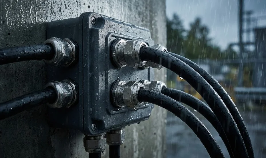
Outdoor Waterproof Enclosures
Outdoor enclosures needing submersion or high ingress protection often use IP68 rated glands. Sizes like M20 et M25 are common for typical power and signal entries.
Material Selection Based on Size & Environment
Material matters as much as size when environmental conditions are harsh.
- Brass: Good mechanical strength and common for control installations.
- Stainless Steel (316): Preferred for marine, offshore, and corrosive sites.
- Nylon / Plastic: Lightweight and cost-effective for non-critical indoor uses; may not be suitable for high temperatures or corrosive environments.
Advanced Sizing Considerations
EMC/EMI Shielding
When cable screening/shielding is required for EMC performance, use metal glands with an integrated EMC clamp or a separate EMC earthing kit.
Multiple Cable Entry Glands
For enclosures with bundled cable entries, use multi-hole plates, grommets, or modular multi-gland solutions sized to the combined cable diameters and required IP rating.
High-Temperature Applications
Select seal materials rated for the expected operating temperature (e.g., silicone or Viton seals for elevated temperatures) and confirm thermal expansion effects on clamping ranges.
Questions fréquemment posées
- 1. How do I know which size cable gland to choose?
- Measure the cable outer diameter (OD), consult a reliable Cable gland size chart, and select a gland whose clamping range includes your cable OD. Confirm thread type and IP rating.
- 2. Is Metric better than PG or NPT?
- Metric (M series) is the global standard in many industries and provides consistent sizing ranges. PG and NPT may be required for legacy equipment or region-specific installations.
- 3. Can I use one size larger “just in case”?
- No. Oversizing a gland can compromise sealing effectiveness and reduce the gland’s IP rating. Always match the cable OD to the specified clamping range.
- 4. What happens if the cable OD is too small?
- If the cable OD is below the gland’s minimum clamping range, the gland will not form a proper seal and ingress protection will be compromised.
- 5. Can I mix thread types?
- Threads are not interchangeable without adapters. Use the appropriate thread type for the enclosure or use a certified adapter designed for the intended application.
- 6. Where can I find engineering-approved charts?
- Consult manufacturer datasheets and engineering catalogs from reputable suppliers such as LAPP or other certified manufacturers for model-specific clamping ranges and performance data.
Conclusion
A precise Cable gland size chart is a fundamental tool for safe, reliable, and code-compliant cable installations. By measuring cable OD accurately, matching the clamping range, selecting the correct thread type, and verifying material and IP requirements, engineers and installers can avoid common pitfalls and ensure long-lasting, high-integrity connections across any industrial environment.
For product-specific charts and model data, always consult manufacturer datasheets.