When it comes to electrical design and industrial procurement, few components are as essential as current transformers (CTs). But if you’ve ever looked at an electrical schematic filled with mysterious lines, dots, and triangles, you might have wondered — what exactly do those current transformer symbols mean?
In this article, we’ll unpack the meaning behind current transformer symbols, explain how to read them in circuit diagrams, and give B2B buyers insights into selecting the right CT for their operations. Let’s turn those schematic symbols into clear, actionable understanding.
What Is a Current Transformer?
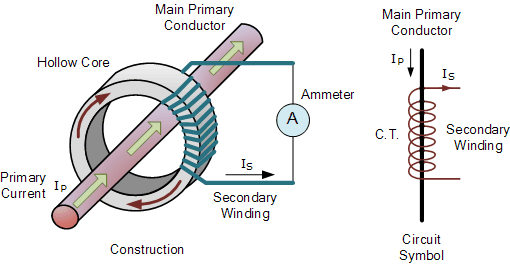
A High Accuracy Mini Split Core current transformer is an electrical device that measures alternating current (AC) by producing a reduced current proportional to the current in its primary circuit. It’s widely used for metering, monitoring, and protective relaying in high-voltage or industrial systems.
Put simply, CTs make it possible to safely measure large electrical currents without directly connecting instruments to high-voltage circuits — a critical safety advantage in industrial applications.
In purchasing terms, the CT is a key measurement and protection component found in everything from power distribution panels à transformer substations et industrial switchgear.
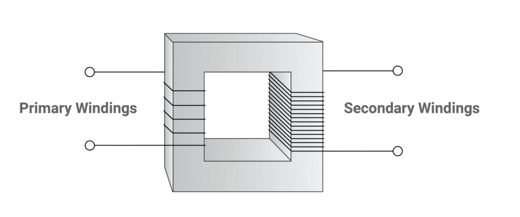
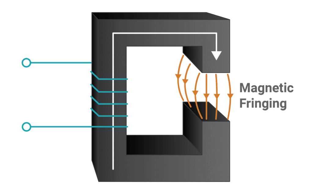
Electrical schematics use symbols to represent the components in a circuit. The current transformer symbol typically consists of two coils — the primary winding and the secondary winding — often shown as parallel or concentric circles. Lines may connect these to the circuit paths they monitor.
Here’s what you’ll often see in drawings:
Symbol Element
Meaning
Typical Notation
Two concentric circles
Transformer core
Often labeled “CT”
Primary winding
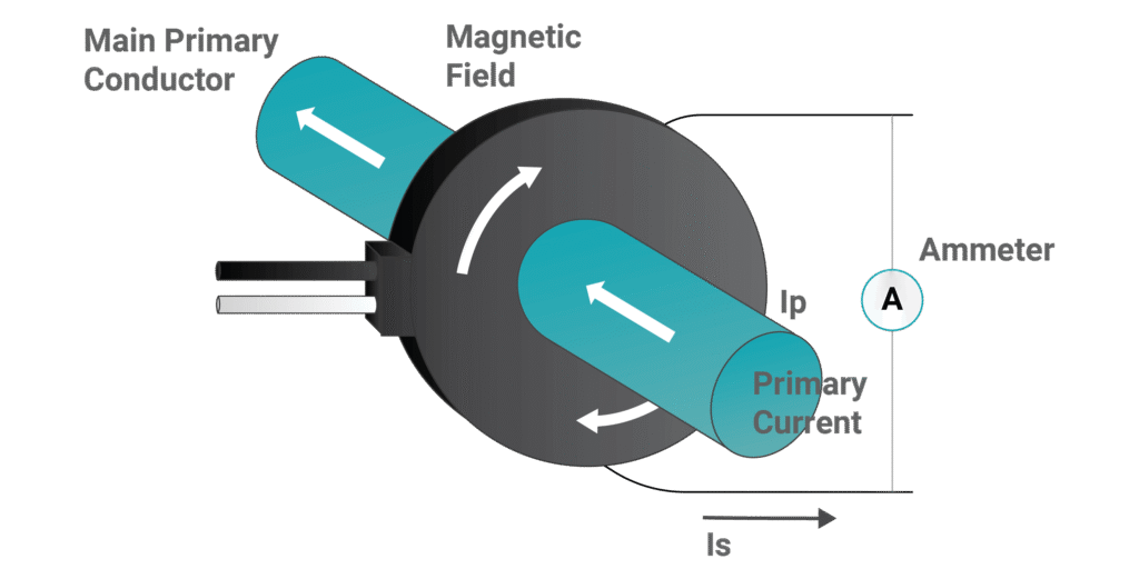
The high-current conductor passing through
Usually a single line
Secondary winding
Output winding connected to meter or relay
Coil or loop symbol
Dot or polarity mark
Indicates winding polarity
Important for connection direction
These elements combine to show the flow direction et ratio conversion between primary and secondary circuits.
Conseil : In some standards, the CT symbol might look different — for example, IEC et ANSI representations have slight variations. Always check the symbol legend on your diagram to confirm the reference standard.
International Standards for Current Transformer Symbols
In global projects, engineers and procurement specialists deal with varying electrical standards. Knowing the standard your equipment follows is crucial.
Standard
Governing Body
Symbol Style
Common Usage Region
IEC 60617
International Electrotechnical Commission
Simplified, modern schematic
Europe, Asie
ANSI Y32.2
American National Standards Institute
More detailed schematic
Amérique du Nord
JIS C0617
Japanese Industrial Standard
Similar to IEC with local variations
Japan, East Asia
Being familiar with these standards ensures consistency across documentation, vendor quotes, and international supply chains. It also helps when comparing technical drawings or verifying CT specifications during procurement.
Why CT Symbols Matter in Industrial Design
If you’re a procurement manager, electrical engineer, or OEM buyer, understanding CT symbols gives you more than just clarity — it affects safety, compliance, and equipment compatibility.
System Compatibility: Prevents misconnection between current and potential transformers.
Efficiency in Design Reviews: Lets technical and purchasing teams communicate with clarity during tenders or audits.
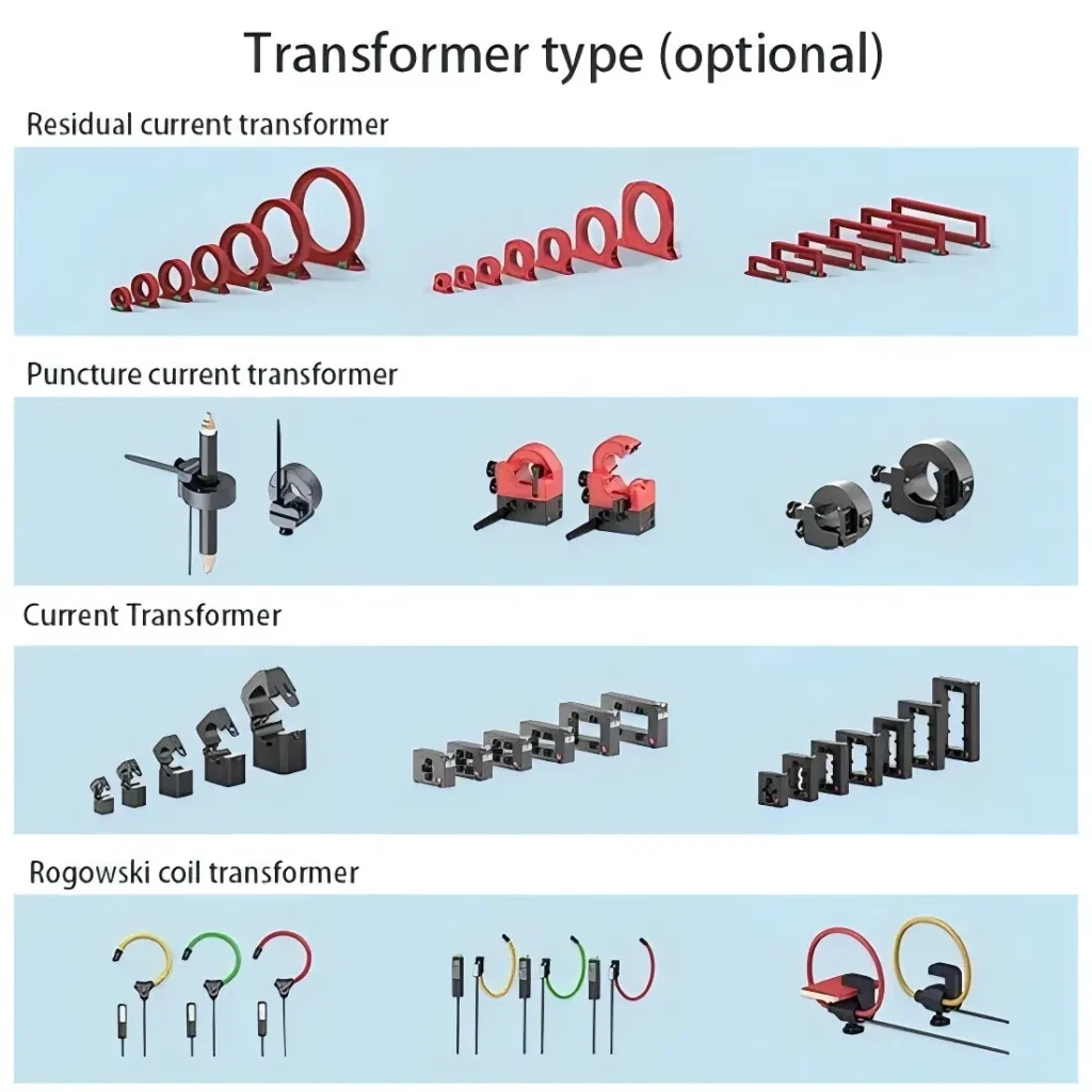
Procurement Accuracy: Knowing what the symbol represents helps you confirm you’re ordering the correct CT type, whether bar-type, wound-type, or split-core.
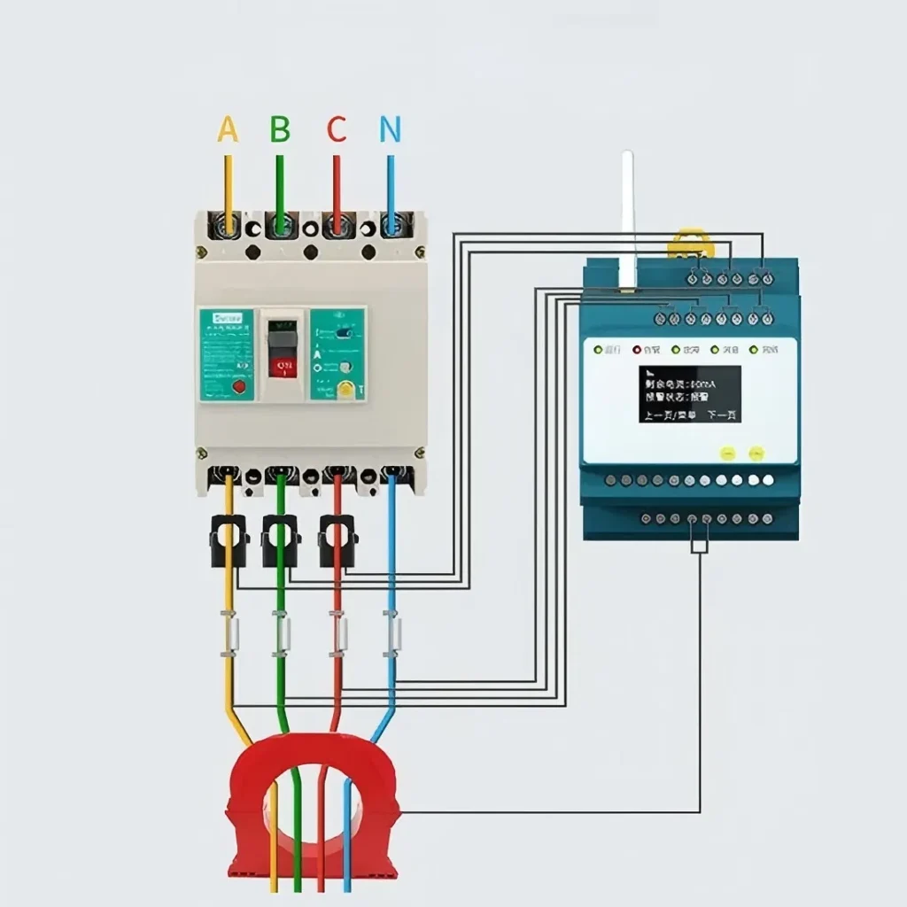
For example, a split-core CT, often found in retrofit installations, might have a distinctive hinged symbol — a clue that the CT can be opened and installed without disconnecting the circuit.
Understanding these details reduces the risk of ordering errors and installation issues.
Types of Current Transformer Symbols and Their Applications
Different CTs serve different purposes, and their symbols reflect this. Let’s explore a few Current Transformer common types that often appear in industrial wiring diagrams et product datasheets.
CT Type
Symbol/Representation
Application typique
Bar-Type CT
Straight line as primary bar through core
High-current busbar monitoring
Wound-Type CT
Coils shown on both primary and secondary
Precision metering
Window-Type CT
Open center, no primary winding drawn
Busduct or cable measurement
Split-Core CT
Hinged circle or open design
Retrofit and maintenance installations
When you see these symbols in electrical schematics or supplier datasheets, they immediately tell you how the CT integrates into your measurement system.
Current Transformer Symbol in Single-Line Diagrams
Single-line diagrams (SLDs) condense complex electrical circuits into simplified line representations. CT symbols in SLDs show where measurement points exist and how energy flows.
Typically, CTs appear at:
Incoming power lines (for grid metering)
Motor control centers (MCCs)
Protection relays for overcurrent detection
The CT symbol in SLDs is typically placed before the circuit breaker or metering device, showing that it senses current upstream.
If you’re a plant maintenance engineer or vendor preparing layout drawings, reviewing CT symbol placement is key for verifying correct load-side orientation and polarity.
Decoding Labeling: CT Ratio and Polarity
Every CT symbol references two important pieces of data — the ratio et polarity.
For example: Label: CT 2000/5A, Class 0.5, 15VA
Let’s decode that:
Paramètres
Meaning
2000/5A
Primary current 2000A, secondary output 5A
Class 0.5
Accuracy class for metering
15VA
Burden rating, indicating load capacity
Understanding these parameters ensures proper system calibration et meter matching. When sourcing CTs for industrial panels, check that the CT ratio aligns with both the rated primary current and the expected secondary instruments (meters or relays).
Many B2B buyers overlook polarity marking in the diagram, which can cause reversed measurements. The symbol’s dot notation helps avoid this — dots or small marks on CT diagrams indicate the same polarity ends of windings.
Common Long-Tail Keywords Worth Knowing
For buyers or electrical engineers looking online for more details, some relevant long-tail keywords include:
“current transformer symbol in circuit diagram”
“CT connection diagram for protection”
“IEC symbol for current transformer”
“CT secondary wiring and polarity”
“industrial CT schematic symbol”
Including these in your search or documentation helps you find the right technical drawings and supplier references.
Buying Current Transformers: What B2B Buyers Should Check
When it’s time to source or procure CTs, symbols alone aren’t enough. You should confirm technical and logistical aspects before placing an order.
Facteur
Why It Matters
Example
CT Ratio
Determines measurement sensitivity
1000/1A or 2000/5A
Accuracy Class
Affects metering precision
Class 0.2, 0.5, 1.0
Burden Rating
Impacts relay performance
10VA, 15VA, 30VA
Insulation Level
Ensures safety at operating voltage
0.72kV, 3kV, 6kV ratings
Mounting Type
Depends on system design
Busbar, panel, DIN-rail
Compliance
Matches your local standards
IEC 61869, ANSI C57.13
If you’re unsure which CT is right for your system, feel free to reach out for detailed datasheets or quote requests — most industrial suppliers provide technical consultation before purchase.
Practical Example: Reading a CT Symbol in a Real Diagram
Imagine an industrial switchboard schematic labeled:
“CT1 – 800/5A, Class 1.0, connected to ammeter A1.”
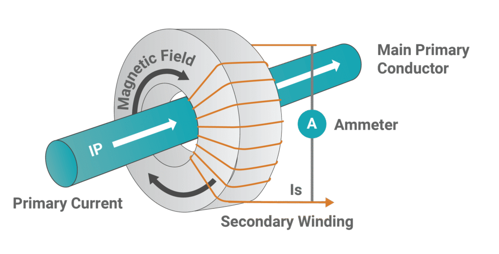
You’d likely see a circular transformer symbol with one line passing through (the primary conductor) and two leads linking to the ammeter symbol. This tells you that CT1 measures current from the line feeding that particular load, with a conversion ratio of 160:1. If 800A flows in the primary, 5A flows in the secondary — an easily measurable current for standard instruments.
By learning to interpret these CT symbols, you bridge the gap between the drawing board and practical installation — a skill every industrial engineer or buyer benefits from.
The next time you open a circuit diagram filled with circles, dots, and letters, take a closer look — those current transformer symbols tell a detailed electrical story. For industrial and procurement teams, interpreting those symbols correctly ensures safety, accuracyet compliance across projects.
Whether you’re specifying CTs for a new substation or checking vendor drawings for approval, mastering these symbols will help you make smarter purchasing decisions et reduce installation risk.
If you’re currently sourcing current transformers or need technical clarification on CT ratings and standards, don’t hesitate to contact your supplier or request a datasheet today — decoding symbols is just the first step toward powering up your project safely and efficiently.
FAQ
Why do CT symbols vary by country?
Different countries use differing electrical standards (IEC/ANSI), which slightly adjust symbol shapes for readability and regulatory consistency.
Can I use the same CT symbol for voltage transformers (VT)?
No. Voltage transformers (VTs or PTs) use different schematic symbols, often with more coil loops and “PT” or “VT” labeling.
How do I identify CT polarity on a drawing?
Look for a dot symbol or K/L marking — this shows where the current enters and exits with the same phase orientation.
What does the CT ratio mean on the symbol?
It’s the conversion factor between the primary and secondary currents, like 1000/5A or 400/1A. It ensures the secondary output stays standardized for instruments.
Are CTs shown in single-line diagrams (SLDs)?
Yes, CTs are usually placed near circuit breakers or metering points on SLDs to illustrate measurement or protection locations.
A current transformers (CT) is a device used to safely measure alternating current in power systems by stepping a large line current down to a much smaller, manageable value in its secondary winding, while keeping the ratio proportional between primary and secondary currents for accurate calculation of the original current. This reduced current can then […]
Product Overview Wilmall Split Core Series for Fast, Non-Invasive Installation Wilmall’s Split Core Current Transformer range is engineered for quick, non-invasive installation in existing electrical systems. These hinged split core CTs enable installers to clamp directly around live conductors or busbars without disconnecting cables, minimizing downtime during retrofit projects. Core Value Proposition: Hinged Design for […]
I. Product Overview & Engineering Design Introduction Solid core current transformers (CTs) are essential instrument transformers designed to provide accurate current measurement and reliable electrical protection. Featuring a robust toroidal core, these through-hole current transformers are widely used in low voltage CT applications to monitor and control electrical systems effectively. The solid core design ensures […]
Nous répondrons à votre demande dans les 24 heures
Nous accordons de l'importance à votre vie privée
Nous utilisons des cookies pour améliorer votre expérience de navigation, vous proposer des publicités ou des contenus personnalisés et analyser notre trafic. En cliquant sur "Tout accepter", vous consentez à notre utilisation des cookies.