Brass Cable Gland Nickel-Plated IP68 Waterproof Industrial Grade
BCG-200 brass cable gland for factories, suppliers, exporters, and distributors. Supports bulk purchase, custom OEM/ODM, wholesale pricing, and private label.
Read MoreImproper cable gland installation accounts for 60% of industrial equipment failures due to moisture ingress, leading to costly downtime and safety hazards. Whether you’re a procurement manager evaluating supplier capabilities or an installation engineer seeking IEC-compliant procedures, this guide provides actionable techniques for achieving IP68-rated watertight sealing.
Cable gland installation must comply with international standards to ensure safety, reliability, and environmental protection. The primary framework is IEC 62444:2010, which specifies construction and performance requirements for cable glands used in electrical installations [web:6]. This standard covers complete cable glands with metric entry threads and establishes testing protocols for mechanical retention, electrical continuity, and environmental sealing.
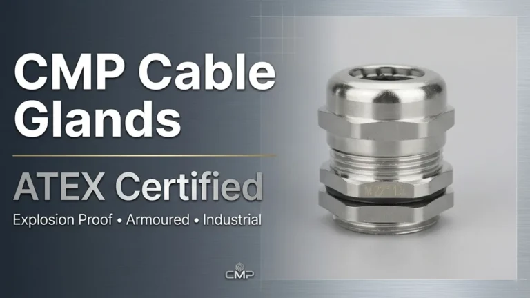
For hazardous environments such as chemical plants or offshore facilities, additional compliance with IEC 60079 (explosive atmosphere protection) and IEC 61892 (offshore applications) becomes mandatory [web:8]. Understanding these standards helps procurement teams verify supplier certifications and ensures installation teams follow proper procedures.
The standard mandates that properly installed cable glands must:
Proper cable gland installation begins with accurate component selection. Match the gland thread type (metric M, PG, NPT, or G thread) to your equipment entry specification. Measure the cable outer diameter precisely and select a gland with the appropriate cable range—typically 2-3mm tolerance for compression-type glands [web:11].
Critical selection factors:
Cable preparation directly impacts sealing effectiveness. Strip the outer cable sheath to expose conductors, leaving sufficient length for equipment termination plus 15-20mm extra for secure gland grip. For armoured cables, carefully separate and prepare wire armour without damaging inner insulation [web:10].
Use proper cable stripping tools rather than knives to prevent conductor damage or insulation scoring that could compromise the seal. Clean any cable lubricant or debris from the stripped area, as contaminants prevent proper compression seal formation.
Disassemble the cable gland and thread components onto the cable in the correct sequence before insertion. The typical order is: locknut, washer, gland body, compression cone/seal, and compression nut [web:13]. This sequence varies by gland design, so consult manufacturer specifications.
For armoured cable glands, additional components include armour gripping rings and sealing washers that must be positioned before final assembly. Missing or incorrect component sequencing is a common cable gland installation error requiring complete disassembly to correct.
Thread the prepared cable through the gland body, ensuring the cable sits centrally within the gland bore. Position rubber or elastomer sealing elements around the cable outer sheath, ensuring full contact around the circumference [web:10]. The sealing element must compress evenly to achieve IP68 rating.
For applications requiring chemical resistance, verify that seal material (NBR, EPDM, or Viton) matches the exposure environment. NBR seals offer general-purpose protection, while EPDM suits outdoor UV exposure and Viton handles aggressive chemicals.
Hand-tighten the compression nut until resistance is felt, then apply final torque using a calibrated torque wrench per manufacturer specifications—typically 5-15 Nm depending on gland size [web:11]. Under-tightening leaves gaps allowing moisture ingress, while over-tightening can damage seals or crack plastic components.
The compression process must deform the seal element sufficiently to fill all gaps while maintaining cable integrity. For armoured glands, tighten the armour locking nut to secure wire armour against the cone, preventing pullout and maintaining earth continuity [web:13].
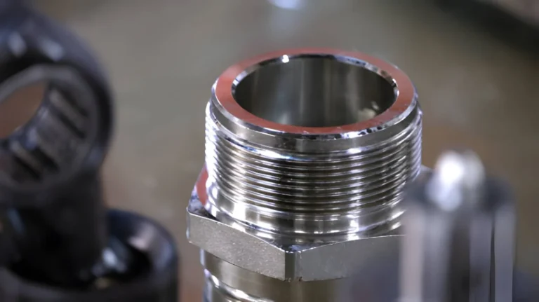
Thread the assembled gland into the equipment enclosure entry, ensuring the thread fully engages. Hand-tighten until the gland seats against the enclosure wall, then apply the locknut from inside the enclosure. Tighten the locknut against the enclosure wall to prevent gland loosening due to vibration or cable movement.
The locknut provides critical strain relief, preventing cable weight or pulling forces from transferring to internal connections. For panel-mount applications, use the appropriate washer configuration to distribute compression forces and prevent panel deformation.
Quality cable gland installation requires verification testing before commissioning. Conduct visual inspection confirming all components are properly seated and tightened. Check for any visible gaps between sealing elements and cable sheath.
Perform pull-testing by applying force to the cable (50-100N for small glands) to verify mechanical retention. For critical applications, conduct water immersion testing to confirm IP rating achievement. Electrical continuity testing ensures proper earth connection for armoured cables [web:11].
Installing cables at the extreme ends of the gland’s cable range prevents proper seal compression. A cable that’s too small won’t compress the seal adequately, while oversized cables prevent full threading of compression components. Specify gland cable ranges conservatively, targeting the middle third of the stated range.
Leaving cable lubricant, dust, or moisture on the cable surface before installation prevents seal adhesion and creates leak paths. Industrial environments often contaminate cables during pulling operations, requiring cleaning before gland assembly. Use clean cloths and appropriate solvents to remove all contaminants from the sealing area.
Mixing gland and seal materials from different manufacturers can result in dimensional mismatches preventing proper sealing. Some “universal” seals don’t meet OEM specifications for compression characteristics. Specify complete gland assemblies from single manufacturers to ensure component compatibility.
Installed cable glands require periodic inspection to maintain sealing integrity. Establish inspection schedules based on environmental exposure—quarterly for harsh outdoor or chemical environments, annually for controlled indoor locations.
Inspection checklist:
Replace glands showing seal deterioration, mechanical damage, or those that have been disturbed during cable modifications. Cable gland installation is not reusable—opening a compressed seal breaks its integrity, requiring complete component replacement.
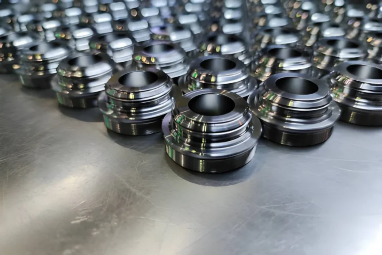
Procurement decisions significantly impact installation success and long-term performance. Specify cable glands from manufacturers providing full IEC 62444 compliance documentation and third-party certification. Request material certifications confirming brass composition, plating thickness, and seal elastomer specifications.
Evaluate supplier quality systems—ISO 9001 certification indicates consistent manufacturing processes. Request sample glands for installation testing before large purchases, verifying ease of assembly and seal compression characteristics. Compare total cost of ownership including installation labor, not just component price, as quality glands install faster and require less rework.
The total cost of poor cable gland installation extends beyond component replacement. Equipment failures from moisture ingress create production downtime averaging 4-8 hours per incident. Emergency repairs cost 3-5× normal maintenance rates, and repeated failures damage equipment reputation with end customers.
Professional installation following IEC standards provides verifiable documentation for quality audits, insurance claims, and warranty compliance. Trained installation teams achieve 98%+ first-time success rates, eliminating expensive rework and reducing project timelines.