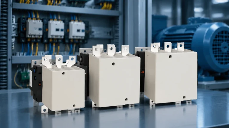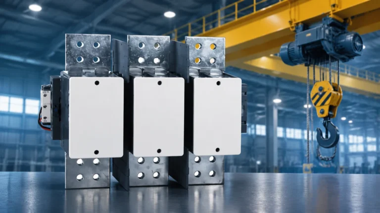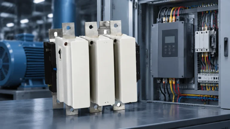

Quick answer: an AC contactor and a DC contactor are not the same device with a different label. An AC contactor lets the arc die at the natural current zero, which happens 100 or 120 times a second, so its arc chute can stay short and cheap. A DC contactor never gets a zero crossing, so it has to push the arc out magnetically into a long splitter stack, carry heavier contacts, and is usually a larger frame for the same current. The coils are also wound differently: an AC coil on a DC supply burns out, and a DC coil on an AC supply will not pull in.
Both devices do the same job. They close a circuit, carry current, and open it again under load. Both are covered by IEC 60947-4-1, both have a coil, a magnetic circuit, main contacts and an arc chute, and both are selected against a utilization category.
The difference is not in the topology. It is in what the current does at the instant the contacts part — and everything else, from the arc chute to the contact mass to the coil winding, follows from that one fact.

AC Contactor vs DC Contactor at a Glance
The table below is the summary most buyers are looking for. Each row is explained in the sections that follow.
| 기능 | AC contactor | DC contactor |
|---|---|---|
| Arc extinction | Natural current zero, twice per cycle | Forced by magnetic blowout and a long splitter stack |
| Arc chute | Short stack of steel plates | Long deionising chamber, often 2–3× the volume |
| Magnetic circuit | Laminated core, shading ring on the pole face | Solid or laminated core, no shading ring |
| Coil inrush | 5–8 × holding current for the first cycles | Smooth L/R rise, no inrush peak |
| Coil noise | Audible hum if the shading ring cracks | Silent in operation |
| Contact mass | Moderate, erosion allowance sized for short arcs | Heavier, higher contact force, larger erosion allowance |
| Poles in series | Rarely used | Standard practice above roughly 250 V DC |
| Rated against | AC-1 / AC-3 / AC-4 at a stated voltage | DC-1 / DC-3 / DC-5 / DC-PV at a stated L/R time constant |
| Size per ampere | Baseline | Larger frame, deeper panel |
| Price per ampere | Lower | Higher |
| Typical loads | Motors, HVAC, pumps, resistive heaters | PV strings, battery racks, DC microgrids, EV charging, DC hoists |
Difference 1 — Arc Extinction
When the contacts of a contactor separate under load, the current keeps flowing through ionised air. This arc is the whole design problem. It is also where AC and DC part company.
On an AC supply the current passes through zero 100 times a second at 50 Hz, 120 times at 60 Hz. At each zero the energy feeding the arc stops for an instant. If the gap has cooled and stretched enough by then, the arc fails to restrike and the circuit is broken. A good AC contactor clears within a half cycle, which is 10 ms at 50 Hz. The arc chute only has to help — a short stack of steel splitter plates that stretches and cools the arc is enough.
On a DC supply there is no zero. The arc burns until the voltage needed to sustain it exceeds the voltage the circuit can deliver. There are only two ways to get there: lengthen the arc, or cool it hard. Practical DC contactors do both at once.
- Magnetic blowout. Permanent magnets or a blowout coil produce a field across the arc. The resulting force drives the arc off the contacts and up into the chute, away from anything it can damage.
- A long splitter stack. Each steel plate the arc crosses adds roughly 20–30 V of arc voltage. Twelve plates in series add 250–350 V, which is why a splitter stack can break a 500 V DC circuit that a two-plate AC chute cannot.
- Sealed gas or vacuum chambers for high current and repetitive duty, where the arc is contained and quenched without venting hot gas into the enclosure.

One practical consequence catches buyers out: on a DC contactor with magnetic blowout, polarity matters. Reverse the supply polarity and the magnetic force drives the arc in the wrong direction, away from the chute and toward the terminals. The contactor still closes and still opens, so nothing looks wrong until the one time it has to break a fault. The polarity marking on the nameplate is there for this reason, not for decoration.
The full mechanical treatment — arc energy budget, time constants, chamber types — is in why DC contactors need special arc extinction.
Difference 2 — Coil Design and Coil Current
The coil is the second place where the two devices cannot be swapped, and it is the one that fails fastest when they are.
An AC coil is wound for a specific impedance at 50 or 60 Hz, on a laminated iron core. Its pole face carries a copper shading ring, a short-circuited turn that produces a flux shifted in phase from the main flux. The point of the ring is that the total pull never passes through zero, so the armature does not chatter at 100 or 120 Hz. When the ring cracks — a common end-of-life failure — the contactor buzzes loudly and the coil overheats.
An AC coil also draws a high inrush current, typically five to eight times the holding current, because the open magnetic circuit has a large air gap and low inductance. Once the armature seats, inductance rises sharply and the current falls. The coil’s thermal design is based on the holding value, not the inrush.
A DC coil sees a constant voltage. The current rises along the L/R time constant and levels off, the magnetic force builds monotonically, and there is no zero crossing to shade, so no shading ring is needed. The coil runs silent. The catch is that pickup current equals holding current, so the coil dissipates its full rated power continuously; many DC contactors therefore include an economiser — a second winding, or a resistor switched in by an auxiliary contact once the armature has sealed — to cut holding losses by 60–90%.

Now the two failure modes that generate most of the support questions we get:
- An AC coil on a DC supply loses its reactance. Only the DC resistance of the winding limits the current, so it draws several times its rated current and the coil burns out in minutes, sometimes seconds. It usually smells of burnt varnish before it fails open.
- A DC coil on an AC supply sees a high inductive reactance it was never designed for. The current is far too low, so the contactor either refuses to pull in or pulls in and chatters. If it does hold, the shading-ring-less pole face gives the armature a 100 Hz force pulsation it cannot absorb.
This is why a coil marked 110 V is not interchangeable with another coil marked 110 V. The voltage matches; the supply type does not. When you order a replacement coil, the supply type is part of the part number.
For the symptom side of this — buzzing, chattering, hot coils that still measure the right resistance — see why contactors buzz 그리고 contactor coil testing.
Difference 3 — Contact Material and Contact Wear
Because the DC arc lasts far longer, it moves far more metal. AC contactor contacts erode slowly and fairly evenly, and the wear is dominated by the making operation — six times rated current on AC-3, but a break at only rated current.
DC arcs do something else. They transfer material directionally: the anode pits, the cathode builds a spike. A DC contactor that has done its rated electrical life often shows one deeply pitted contact and one with a proud, rough crown, which is normal for the duty and not a defect. What it does mean is that a DC contactor needs more contact mass, higher contact force to break through surface oxide and to resist welding, and a material chosen for erosion resistance rather than for low contact resistance alone.
The practical rule: do not judge the remaining life of a DC contactor with an AC contactor’s wear table. The thickness limits, the wear pattern and even the inspection interval are different. Material selection for both types is covered in AgSnO2 vs AgNi vs AgCdO, and measurement on site in how to measure contact wear.
Difference 4 — Size, Weight and Panel Space
A DC contactor of the same current rating is physically larger, and the gap widens with voltage. The arc chamber is longer, the contacts are heavier, and the magnetic circuit is bigger. On a 600 V DC string the difference is not marginal — a DC device may need twice the panel depth of the AC contactor a buyer instinctively compares it to.
Two knock-on effects matter at the design stage. First, series-connected poles consume terminals and wiring space, not just device width. Second, a bigger device in the same enclosure runs hotter, so temperature derating bites earlier. The correction factors for ambient, altitude and enclosure are in contactor derating; apply them to the DC device with more margin, not less.
Utilization Categories: AC-1 to AC-4 vs DC-1, DC-3, DC-5 and DC-PV
A contactor current rating means nothing without a utilization category. IEC 60947-4-1 defines them separately for AC and DC, and the DC categories also carry a time constant, because that is what determines how hard the break really is.
| 카테고리 | Load | What it means in practice |
|---|---|---|
| AC-1 | Non-inductive or slightly inductive | Resistive heating, distribution. The easy case. |
| AC-3 | Squirrel-cage motor, start and run | Make 6 × Ie, break 1 × Ie. The default motor rating. |
| AC-4 | Squirrel-cage motor, inching and plugging | Make and break 6 × Ie. Heavy duty, much shorter life. |
| DC-1 | Non-inductive or slightly inductive | Resistive DC loads, and the category most often quoted at low voltage. |
| DC-3 | Shunt-wound motor, starting and plugging | Frequent starting and inching of DC drives. |
| DC-5 | Series-wound motor | Hoists, traction, and the harshest DC motor duty. |
| DC-PV | Photovoltaic array | Added in later editions for PV strings, where the source current is limited and the open-circuit voltage is high. |
Two notes that save arguments. A DC rating is always quoted at a stated time constant — 1 ms, 7.5 ms or 15 ms in the standard test values. A contactor rated 100 A at L/R = 1 ms may be rated 40 A at 15 ms for the same voltage. And auxiliary contacts follow a separate scheme entirely: AC-15 vs DC-13 explains why the same block has a 10 A AC rating and a 1 A DC rating. The AC categories in detail are in AC-1 to AC-4 explained.
Can You Use an AC Contactor for DC?
Not as a drop-in substitute at its AC rating. This is the single most common mistake in the whole comparison, and it usually surfaces months later as a welded contactor rather than as an obvious failure.
There are four reasons: the arc chute is too short, there is no blowout magnet, the AC-3 rating is not a DC rating at any voltage, and the contact mass was sized for arcs that last half a cycle. On a DC supply the arc simply hangs on the contacts until something gives — usually the contacts themselves, welding closed.
What is legitimate:
- Use the printed DC-1 rating. Many IEC AC contactors carry a DC-1 rating at 24 or 48 V DC on the nameplate. That rating is real and can be used — at the category and voltage printed, and nowhere else.
- Put poles in series on a genuine DC device. Series connection splits the arc into multiple gaps and adds arc voltage, which is why DC contactors for 600 V and 1000 V are commonly specified with two or four poles in series. It works because the gaps are in series with the same current.
- Do not put poles in parallel to gain current. The poles never share equally, because contact resistance and closing timing differ, so one pole carries most of the load and fails first.
Where the reverse swap is concerned — a DC contactor used on AC — the device will normally break the AC load without difficulty, because AC is the easier duty. The obstacle is the coil, which will not work, and the cost, which is unnecessary. Sizing for 600 V and 1000 V DC systems, including the derating arithmetic, is in DC contactor selection.
Control Circuits: What Actually Feeds the Coil
“AC vs DC” is really two separate questions that get mixed together, and the confusion in most selection conversations comes from answering one when the other was asked.
- The load circuit — what the main contacts switch. This decides whether you need an AC contactor or a DC contactor.
- The control circuit — what energises the coil. This decides the coil, and it is independent of the first question.
You can perfectly well have a DC contactor whose coil is fed from a 230 V AC control circuit through a small rectifier, or an AC contactor with a 24 V DC coil driven by a PLC output. Neither is unusual.

AC control circuits
The classic machine and switchgear arrangement: a control transformer taps two phases and produces 110 V or 230 V AC for the coil circuit. There is no battery, no charger and almost no maintenance, which is why it survives in industrial panels and distribution switchgear. Long control cable runs are its weak point — capacitive coupling can hold a coil at a voltage too low to pull in but high enough to keep it buzzing, the so-called phantom voltage.
DC control circuits
Two distinct families share the name. Inside a machine panel, 24 V DC comes from a switch-mode power supply and feeds contactor coils, relays and PLC outputs. In a substation or a process plant, 110 V or 220 V DC comes from a battery maintained on float charge, so the coil circuit keeps working while the AC supply is collapsing — the reason protection and breaker control circuits are DC.
For coil selection the practical points are the same in both families. Check the coil consumption against the driving output, because a 24 V DC contactor coil can draw several watts and a small PLC output will not survive the inrush. Fit the correct surge suppressor for the coil type — an RC network for AC, a diode or varistor for DC — because the wrong one either fails to clamp the inductive kick or slows the drop-out enough to be dangerous. The options are set out in selecting a surge suppressor for contactors.
Mixed AC and DC control panels
Once a panel carries both, three habits prevent most callbacks: keep AC and DC control wiring in separate ducts with separate labels, mark coil supply type on the terminal shroud as well as the drawing, and never let a spare core decide the coil voltage. A contactor with the right voltage and the wrong supply type is the most expensive cheap mistake in a control panel, because it fails on energisation and takes the commissioning day with it.
Selection Checklist: Seven Questions Before You Order
- What is the load? Motor, resistive heater, PV string, battery rack, capacitor bank. Each maps to a different utilization category.
- What is the source, exactly? AC or DC, nominal voltage, and for DC the L/R time constant of the circuit. Without the time constant a DC rating cannot be interpreted.
- Does it break current, or only isolate? A contactor used as an isolator after a drive has stopped faces a far easier duty than one that interrupts a running load.
- Which utilization category applies? AC-3 for a motor, AC-4 for inching and plugging, DC-1 for resistive DC, DC-5 for a series motor, DC-PV for strings.
- What feeds the coil? Voltage and supply type, plus available VA or watts from the driving output. This is a separate decision from questions 1 to 4.
- What duty cycle and electrical life are required? Operating frequency and expected operations decide the frame size as much as the current does.
- What is the environment? Ambient temperature, altitude, enclosure volume and dust. Apply the derating factors before you finalise the frame.
If you are sizing an AC device specifically, the motor-side arithmetic and the standard chart are in AC-3 contactor rating chart 그리고 how to size and select a contactor.
Where Each Type Wins
AC contactors dominate wherever the supply is already AC and the load is a three-phase induction motor: pumps, fans, compressors, conveyors, HVAC plant, and resistive heating. They are also the only sensible choice for capacitor switching, which needs a dedicated AC-6b device with damping resistors rather than a standard motor contactor.
DC contactors own the applications where the DC cannot be avoided: PV strings at 600 V and 1000 V, battery racks and BESS containers, DC microgrids, EV charging equipment, DC crane and hoist drives, telecom −48 V plant, and the DC output of electrolysis and plating rectifiers. Where the DC motor is a slip-ring machine on a hoist, the AC-side duty is AC-2 and the DC-side duty is DC-5 — two different devices in the same drive train.
Bottom Line
An AC contactor is designed around a current that gives up twice per cycle. A DC contactor is designed around a current that never does. That single difference drives the arc chute, the contact mass, the frame size, the price, and the coil — and it is why the two are specified against different utilization categories and different test conditions.
Get three things right and the rest follows: the load current and its category, the L/R time constant if the supply is DC, and the coil voltage with its supply type. Everything else on a data sheet is downstream of those three.
자주 묻는 질문
What is the main difference between an AC contactor and a DC contactor?
The arc. An AC contactor relies on the current passing through zero 100 or 120 times a second, which lets the arc extinguish on its own within half a cycle. A DC contactor has no zero crossing, so the arc must be driven out magnetically into a long splitter stack. That drives everything else: a longer arc chamber, heavier contacts, a larger frame and a differently wound coil.
Can I use an AC contactor for a DC motor?
Not at its AC rating. An AC contactor used to break DC will usually weld its contacts closed, because there is no zero crossing to put the arc out and its arc chute is far too short. The only legitimate use of an AC contactor on DC is a DC-1 rating printed on the nameplate at a specific low voltage such as 24 V or 48 V DC.
Why does an AC coil burn out on a DC supply?
An AC coil is wound for a specific impedance at 50 or 60 Hz, and that reactance is what limits its current. On DC there is no reactance, so only the winding resistance limits the current. The coil draws several times its rated current and overheats within minutes. A DC coil on an AC supply fails the opposite way: the reactance is far too high, so the contactor will not pull in or pulls in and chatters.
Is a DC contactor bigger than an AC contactor of the same rating?
Yes, usually. The arc chamber has to be long enough to stretch the arc until its voltage exceeds the system voltage, which means more plates and more volume, and the contacts carry more mass to survive the erosion. Above a few hundred volts the difference is significant, and a DC device may need two to four poles in series as well.
What do DC-1, DC-3 and DC-5 mean on a DC contactor?
They are utilization categories from IEC 60947-4-1. DC-1 covers non-inductive or slightly inductive loads, DC-3 covers shunt-wound motor starting and plugging, and DC-5 covers series-wound motors such as hoists and traction drives. Each DC rating is quoted at a stated L/R time constant, because the same contactor has very different breaking capacity at 1 ms and at 15 ms.
Do I need a DC contactor for a 48 V battery system?
Often not. At 24 V or 48 V DC many standard AC contactors carry a genuine DC-1 rating on the nameplate, and that rating can be used as printed. The judgment call comes with the current and the inductance of the load: a resistive 48 V load is easy, a battery bank with high prospective fault current or an inductive load is not. Check the nameplate DC rating before assuming either way.
WILMALL supplies AC contactors from 9 A to 800 A in the CJX2, CJX2-F, LC1-D and 3TF frames, together with replacement coils, auxiliary contact blocks and mechanical interlocks. Send us the load, the supply and the utilization category and we will confirm the frame — including, where the duty is DC, whether the job belongs to a DC device rather than a derated AC one. Start from the AC contactor range, or read contactor cross reference if you are replacing an existing unit.