Contactor on VFD Input vs Output: What Actually Changes
Published: Author: Lisa
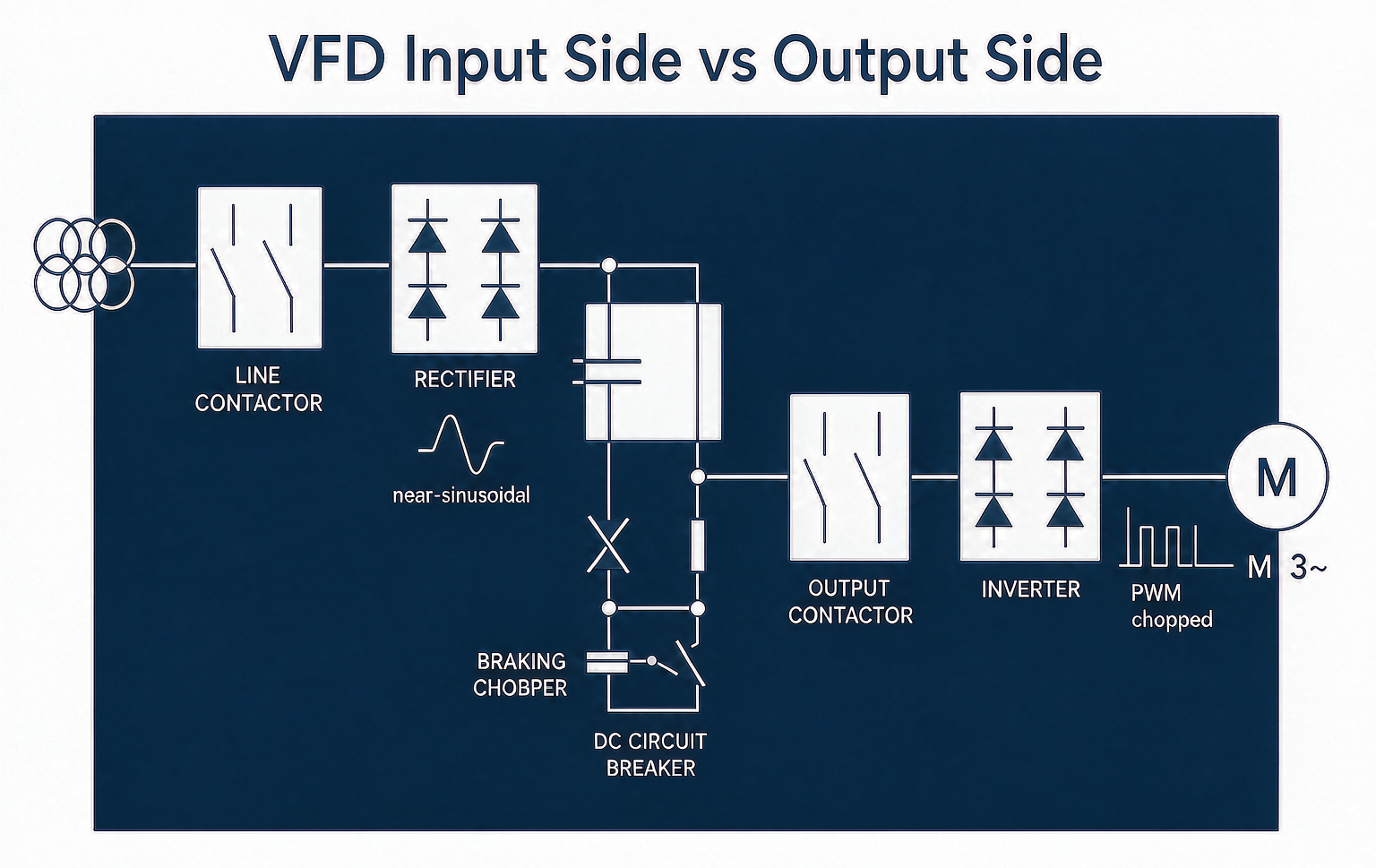
A contactor for VFD duty raises a question that specifiers answer wrongly surprisingly often: can you put a standard AC contactor on the input side, the output side, both — or neither? The two positions are not interchangeable, because the drive transforms the electrical environment in front of and behind it. Input-side contactors see nearly clean power; output-side contactors see PWM-chopped voltage, harmonic-rich current, and sometimes a DC bus behind them.
This guide separates the two applications: what changes electrically on each side, when the contactor needs no special rating, when it must be treated as AC-4 or even DC switching, and the cases where a contactor should not be in the circuit at all. The utilization categories that drive the selection are defined in the AC-1 to AC-4 guide, and the deeper AC-3/AC-4 split for drive-adjacent duty is in the AC-3 vs AC-4 comparison.
PWM-chopped voltage with high dv/dt, voltage spikes at cable and motor
Current waveform seen
Harmonic-rich (6-pulse rectifier current, THDi 30–80% depending on choke)
Fundamental plus carrier-frequency ripple; RMS slightly above motor current
Switching duty
Make: drive inrush (DC bus pre-charge usually limits it). Break: magnetizing current if drive stopped under no load
Make/break: motor current — but must never open a running load (see below)
Utilization category to select on
AC-1 or AC-3 with harmonic heating derating
AC-3 for isolation/backup duty; AC-4 only if it actually does plugging/inching — which it should not on a drive
Main purpose
Isolation, disconnect, protection coordination
Bypass, changeover (DOL↔drive), isolation for maintenance
The core principle behind the whole guide: the VFD should start and stop the motor, not the contactor. A contactor that opens while the drive is powering the motor interrupts current into a load that the drive will fight to keep supplying — and depending on the drive’s protection, this is either a nuisance trip or an arc event at the contacts.
Input-Side Contactor: The Easy Position, With Three Catches
On the line side, the contactor is essentially a disconnect and protection interface. The drive’s rectifier draws harmonic-rich current, which heats the contactor’s conductive parts more than a sinusoidal RMS-equivalent current would. Select with:
Harmonic derating: for 6-pulse drives without a DC choke, size the contactor for roughly 1.2–1.4× the drive’s rated input current; with a DC choke or line reactor, 1.1–1.2× suffices. The extra margin absorbs the skin-effect and crest heating that the RMS number hides.
Inrush check: the drive’s DC bus pre-charge circuit limits input inrush on most modern drives, but verify the datasheet — some drives without pre-charge limiting (or with failed pre-charge relays) draw line-frequency peaks that weld contact tips on make.
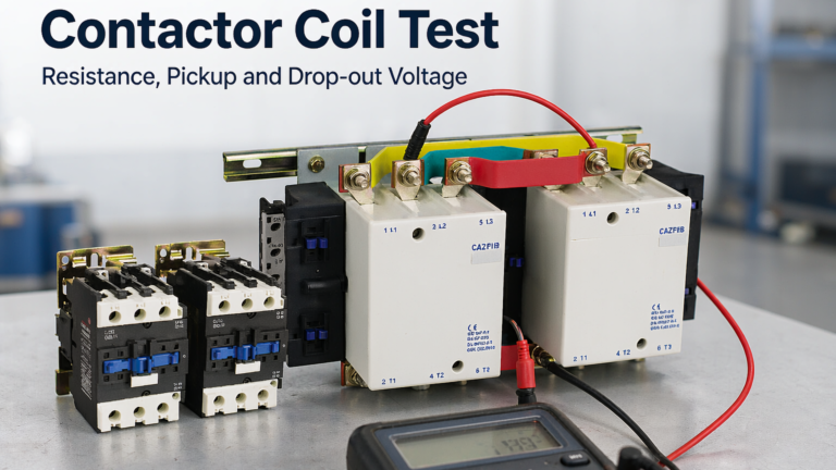
Coil-side reality: if the input contactor switches the drive on and off routinely as a start method, it is cycling a capacitive DC bus through pre-charge every time — pre-charge resistors and relays age, and the contactor sees repeated makes. Use the drive’s enable input for run/stop; keep the input contactor for isolation and protection. Control-supply behavior in that switching chain is covered in the coil test guide.
Many installations also require an input disconnect for lockout — a contactor can serve, but it is not a visible-break isolator; safety codes treat these differently, and a maintenance disconnect is usually a load-break switch, not a contactor.
Output-Side Contactor: The Position That Breaks Devices
Between the inverter and the motor, the voltage is a pulse train — typically 2–16 kHz carrier — riding on the fundamental. Three consequences:
The contactor’s contacts are not designed to switch this waveform. Opening under load interrupts not the fundamental current but a current the drive actively regulates; the drive responds to the load loss with a fault or, worse, keeps modulating into an arc. Contact erosion on output-side switching under load is rapid and unpredictable.
Insulation stress: PWM dv/dt of several kV/µs stresses the contactor’s inter-turn and phase-to-phase insulation at the motor end, where reflected waves can double the voltage on long cables. A contactor in this position should be rated for the drive system’s insulation coordination — this is a real constraint on 690 V drives with long motor cables.
Carrier-frequency ripple heating: the motor current ripple adds I²R heating beyond the fundamental; size with the same 1.1–1.4× margin as the input side depending on carrier frequency and cable length.
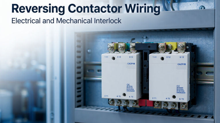
When an output contactor is legitimate: closed before the drive is enabled and opened only after the drive has stopped (isolation for maintenance); bypass/changeover schemes where the motor runs either DOL or from the drive (never both); and switching between multiple motors on one drive — where the drive must be disabled during the changeover by interlock, not trusted to the operator. The interlock discipline for changeover schemes is the same hardware logic used in reversing contactor wiring.
Bypass and Changeover Schemes: The Most Common Real Application
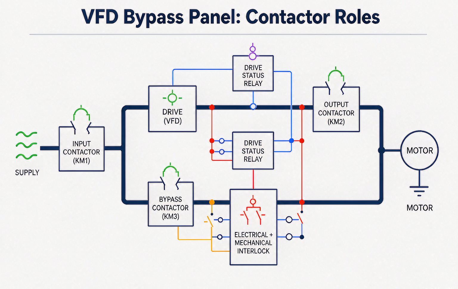
HVAC and pumping plants often run the motor normally through the drive, with a bypass starter for drive-fault operation. The contactor duties in a bypass panel:
Contactor in the scheme
Duty
Selection category
Drive input contactor
Connects drive to supply; isolation
AC-1/AC-3 with harmonic margin
Drive output contactor
Connects drive output to motor — closed before enable, opened after stop
AC-3, sized with PWM ripple margin
Bypass contactor
Connects motor directly to supply (DOL run)
AC-3 for the motor’s DOL duty — full starting current, real AC-3 make
Changeover interlock
Ensures drive output and bypass are never closed together
Electrical + mechanical interlock kit; mandatory
The bypass contactor is the one doing honest AC-3 work — it starts the motor across the line. Size it for the motor, not the drive. And the interlock between output and bypass contactors is safety-critical: closing the bypass onto a drive-fed motor back-feeds the inverter output, which destroys most drives. Interlock failure in a bypass panel is a drive-killer, not a nuisance.
When the Switching Is Actually DC: Braking and Bus Circuits
Two drive-adjacent circuits switch DC, and contactors selected on AC plates fail in them:
DC injection braking: some drives apply DC to the motor for braking; if a contactor sits between drive and motor during injection, its contacts see DC at the injection current. Opening DC under load sustains an arc that AC contacts cannot extinguish at zero crossing — the physics and the required arc management are covered in the DC arc extinction guide.
Braking resistor / chopper circuits: the chopper switches DC pulses; any contactor in that path is a DC switching device, full stop. Do not install a standard AC contactor in a braking resistor circuit.
Dynamic braking contactors in older schemes: same rule — verify what the contacts actually interrupt before reusing a panel design.
Selection Worked Example: 30 kW Pump, Drive with Bypass
A 30 kW / 400 V pump: motor FLC ≈ 57 A, drive rated input ≈ 62 A (6-pulse, with DC choke), bypass DOL starting current ≈ 8× FLC.
Input contactor: 62 A × 1.15 (DC choke installed) ≈ 71 A → next frame at AC-1/AC-3, e.g., an 80 A frame. Verify the drive’s input inrush spec is inside the contactor’s make rating.
Output contactor: motor current 57 A with PWM ripple margin ×1.15 ≈ 66 A → 80 A frame, AC-3, closed-before-enable / opened-after-stop sequencing via the drive’s status relay.
Bypass contactor: motor DOL duty, 57 A AC-3 with full starting make → 80 A frame AC-3; if the pump starts frequently under head pressure, check AC-4 exposure from valve sequencing.
Interlock: electrical cross-coupling plus mechanical interlock kit between output and bypass contactors, with the drive’s ready/status relay gating the bypass branch.
인증: confirm coil-terminal voltage at all three contactors under the panel’s real switching conditions — the pickup margin test in the coil test guide catches undersized control supplies in multi-contactor panels.
Repeated pre-charge cycling ages drive components; contact makes under capacitive inrush
Start/stop via drive enable; contactor for isolation only
Opening the output contactor while the drive is running the motor
Drive fault or sustained arc at the contacts; unpredictable erosion
Interlock: output contactor closes before enable, opens after drive stop
Sizing drive-side contactors on motor FLC alone
Harmonic and ripple heating runs contacts hot; shortened life
Apply 1.1–1.4× margin depending on choke/reactor and carrier frequency
Closing a bypass contactor onto a drive-fed motor
Back-feed into inverter output; destroyed drive
Electrical + mechanical interlock between output and bypass, drive status gating
Standard AC contactor in a braking or DC injection path
DC arc not extinguished at opening; welded contacts
DC-rated switching device or remove the contactor from the DC path
Ignoring reflected-wave voltage on long motor cables
Insulation stress on output contactor and motor; premature insulation failure
Check insulation coordination for the drive/motor/cable system; consider dv/dt filtering on long runs
결론
Input side and output side are different jobs. The input contactor is an isolation and protection interface — select it on harmonic-heated current, and let the drive do the starting. The output contactor is a sequencing device — closed before enable, opened after stop, never a switching element for a running load, with the bypass interlock treated as drive-protection equipment. Where the circuit is DC — braking, injection, chopper paths — leave standard AC contactors out entirely. Size both with the margins above, verify the coil-supply reality under real switching conditions, and the drive-adjacent contactor stops being the panel’s least-understood component. Browse the AC contactor category for frames across the range, and the CJX2-F series contactors for the larger drive-duty frames.
자주 묻는 질문
Do I need a contactor between the VFD and the motor?
Only for a specific purpose: maintenance isolation, bypass/changeover, or multi-motor selection. It must close before the drive enables and open after the drive stops — never used to start/stop the motor under drive power.
Can I start and stop the motor with the input contactor instead of the drive?
Technically possible and electrically safe for the contacts, but it cycles the drive’s DC bus pre-charge on every operation and ages drive components. Use the drive’s enable input for run control; keep the contactor for isolation.
What size contactor for a VFD input?
1.1–1.2× the drive’s rated input current with a DC choke or line reactor, 1.2–1.4× without. The margin covers harmonic heating that the RMS current figure hides.
Why can’t the output contactor switch the motor on and off?
The drive regulates current into the motor; opening under load either trips the drive or sustains an arc at contacts not designed to interrupt a regulated PWM-fed load. Repetitive under-load switching erodes contacts rapidly and unpredictably.
Is the contactor duty on a drive output AC-4?
No — AC-4 applies to plugging and inching duty, which the output contactor should never perform on a drive. It is AC-3 isolation duty; the bypass contactor in a changeover panel is the one doing real AC-3 starting work.
What happens if the bypass contactor closes while the drive is running the motor?
The supply back-feeds the inverter output through the bypass contacts, which destroys most drives. This is why electrical plus mechanical interlocking between output and bypass contactors, gated by the drive status, is mandatory in bypass panels.
The full reversing starter: power wiring with two phases swapped, cross-coupled NC electrical interlock, mechanical interlock backstop, 50–100 ms dead time, and why weld detection is the layer no interlock provides.
Resistance screens the winding, pickup voltage proves it will seat on a sagging bus, drop-out proves it will release. Reference bands, IEC windows, and the five root causes behind burnt coils.
Four measurable wear indicators with instruments, thresholds and baselines: 4-wire micro-ohm resistance, tip thickness, overtravel, and IR temperature rise — and the judgment line between new tips and a new contactor.