


인코더 기호: 엔지니어링에서 인코더 기호를 이해하고 사용하기 위한 가이드
목차
When you’re working with automation, robotics, or industrial control systems, you’ll often come across the term “encoder.”
But have you ever stopped to wonder what the encoder symbols means in technical diagrams?
Let’s break it down together—so the next time you see an encoder symbol, you’ll know exactly what you’re looking at and why it matters.
What Is an Encoder Symbol?
An encoder symbol is a standardized graphic used in electrical and automation schematics to represent an encoder component.
Just like a musical note tells a musician what to play, the encoder symbol tells engineers and technicians what’s happening in the circuit.
It’s a visual shorthand that helps everyone speak the same technical language, no matter where they’re from.
International Standards for Encoder Symbols
You might think every company draws these symbols their own way, but that would be chaos. T
hat’s why organizations like the International Electrotechnical Commission (IEC) created standards—specifically IEC 60617—to make sure encoder symbols look and mean the same thing everywhere.
In the United States, you’ll also see standards from ANSI and IEEE, but IEC 60617 is the global go-to.
According to these standards, an encoder symbol usually appears as a rectangle (representing the device) with input and output terminals.
For rotary encoders, you’ll often see a small circle or arc attached, showing the rotating shaft.
Sometimes, the symbol includes arrows for direction or labels like “ENCODER” to make things crystal clear.
Common Forms of Encoder Symbols
Not all encoders are created equal, and neither are their symbols. Here’s what you’ll typically find:
- Rotary Encoder Symbol: A rectangle with a protruding circle or arc, sometimes with an arrow indicating rotation.
- Linear Encoder Symbol: A rectangle with parallel lines or a straight arrow, representing linear movement.
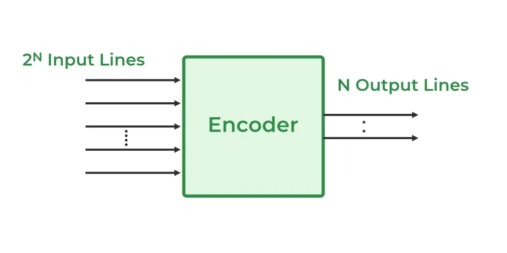
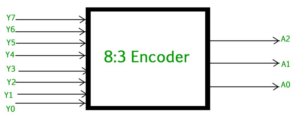
- Digital Encoder Symbol: For logic circuits, you might see a triangle or rectangle with multiple inputs and fewer outputs, labeled with the number of lines (like “8-to-3”).
You’ll also spot variations for incremental and absolute encoders. Incremental encoder symbols may include extra lines for reference (like the Z-channel), while absolute encoders might feature additional labels or a unique outline.
How to Read and Draw Encoder Symbols
When you see an encoder symbol on a schematic, pay attention to:
- Inputs and Outputs: These show how the encoder connects to the rest of the system.
- Labels: Words like “ENCODER,” “ABS,” or “INC” help you spot the type.
- Arrows or Circles: Indicate movement direction or rotation.
If you’re drawing your own diagrams, stick to the standards. Use clear rectangles, mark all terminals, and add any necessary labels. This keeps your documentation clear and professional.
Encoder Symbol in Practical Applications
Let’s get practical. Imagine you’re reading a control panel diagram for a conveyor system. You’ll see the encoder symbol right next to the motor, with output lines leading to a PLC. In a robot arm schematic, the encoder symbol sits at each joint, showing how the system tracks position and movement.
Case in point: If you’re troubleshooting why a conveyor isn’t stopping where it should, tracing the encoder symbols in the wiring diagram helps you quickly find the right connections and signals.
Encoder Symbol and Related Circuit Symbols
Encoders aren’t the only devices with special symbols.
You’ll also run into decoders, sensors, and transducers. While they might look similar—a rectangle here, a triangle there—each has its own unique features.
For example, a decoder symbol usually has more outputs than inputs, while a sensor symbols might include a wave or arrow. Always double-check the labels and context to avoid confusion.
결론
Understanding the encoder symbols isn’t just about reading diagrams—it’s about speaking the universal language of engineering.
Whether you’re designing a new system, troubleshooting an old one, or just trying to make sense of a complex schematic, knowing what the encoder symbol means will save you time and headaches.
So next time you spot that little rectangle with a circle or arrow, you’ll know: that’s the heartbeat of precision motion in your automation system.
자주 묻는 질문
Why do we use standardized encoder symbols?
Standard symbols keep diagrams clear and consistent, making global collaboration possible.
Where can I find the official encoder symbol?
최신 기호 정의는 IEC 60617 또는 업계에서 선호하는 표준을 확인하세요.
How can I tell if a symbol is for an incremental or absolute encoder?
인크리멘탈 인코더에는 참조 채널이 표시되고 앱솔루트 인코더에는 고유한 표시가 있을 수 있으므로 라벨이나 추가 줄이 있는지 확인합니다.