How to Choose a Modular Contactor: 7 Specifications That Matter
Published: Author: Lisa
Learning how to choose a modular contactor is mostly a sequencing problem. Most wrong selections come from starting at the wrong end — reading the biggest ampere number on the front of the device and working backwards from there. The ampere figure is the last thing you should compare, not the first, because it only means something once you know the duty, the voltage and the mounting conditions behind it.
This guide walks the seven specifications that decide whether a modular contactor survives ten years in a distribution board or welds its contacts shut in the first month. It covers the utilization categories that replaced “just add 25%”, how to derate for a real enclosure, the coil-drive traps that catch PLC and building-automation integrators, and a worked example you can follow with your own load figures.
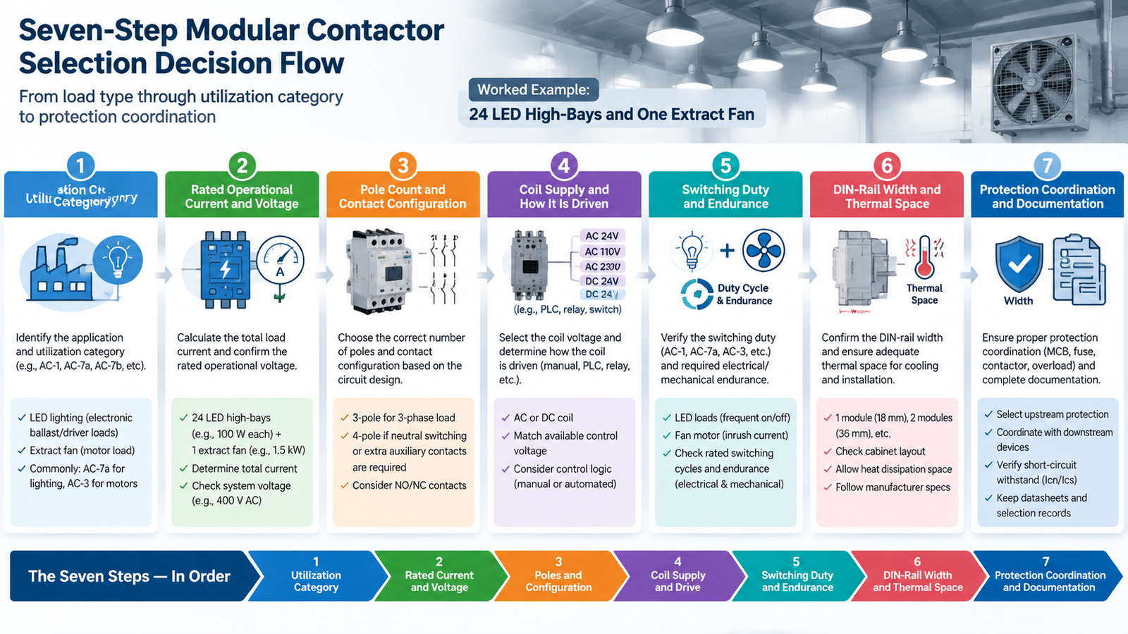
The Short Answer: Seven Specifications, In Order
A modular contactor is defined by seven specifications, and each one constrains the next. Work them in this order and most of the range eliminates itself before you reach a datasheet comparison table.
Utilization category — what kind of load is being switched (AC-7a, AC-7b, AC-7c, AC-7d).
Rated operational current and voltage — at that category, in that enclosure.
Pole count and contact configuration — how many conductors, and NO or NC.
Coil supply and how it is driven — AC, DC or wide-range, and what the controller can source.
Switching duty and endurance — operations per hour and expected operating life.
Rail width, terminals and thermal space — the physical budget you actually have.
Protection coordination and documentation — what protects the contactor, and what the project must submit.
사양
Question it answers
Where the answer comes from
1. Utilization category
What does the contact have to interrupt?
Load type and start behaviour
2. Current and voltage
How much current, at which voltage, at what ambient?
Load calculation plus enclosure conditions
3. Poles and contacts
Which conductors are switched, and in what normal state?
Circuit design and local wiring rules
4. Coil supply
What turns the device on, and can that source drive it?
Controller output and control-circuit design
5. Switching duty
How often, and for how many cycles?
Operating schedule and maintenance policy
6. Physical fit
Does it fit, and can it stay cool?
Board layout drawing
7. Protection
What clears a fault, and what proof is required?
Protection study and project specification
Specification 1: Utilization Category — AC-7a, AC-7b, AC-7c or AC-7d
The utilization category describes the switching stress the contact must survive, not the steady-state current it carries. Modular contactors fall under the household-and-similar scope of IEC 61095, which uses the AC-7 family of categories rather than the AC-1 to AC-4 set used for industrial motor duty.
카테고리
Load it covers
Typical examples
Current limit in scope
AC-7a
Slightly inductive or resistive loads
Resistance heating, suitable lighting loads
Up to 63 A
AC-7b
Motor loads in household and similar applications
Fans, pumps, small compressors
Up to 32 A
AC-7c
Compensated electric-discharge lamp control
Compensated discharge lighting circuits
Up to 32 A
AC-7d
LED lamp and LED control-gear switching
LED luminaires and LED drivers
Expressed as rated power
The AC-7a downgrade trap
This is the single most expensive mistake in modular contactor selection. A device published as “63 A” may carry that figure only in AC-7a. Put the same device on a fan or pump and the usable rating can fall dramatically, because motor starting and interruption impose a different electrical stress on the contacts than a resistive load does.
The scope numbers above make the gap concrete: IEC 61095 covers AC-7a up to 63 A but AC-7b only up to 32 A. A 63 A AC-7a contactor is not, and cannot be assumed to be, a 63 A motor contactor. There is no universal conversion factor between the categories — the ratio is model-specific and depends on voltage, ambient and grouping. Use the manufacturer’s published table for the exact model.
AC-7d and the LED inrush problem
LED luminaires are not resistive loads. The driver input stage is capacitive, so switching on a bank of LED fittings produces a short, steep inrush that can peak far above the steady-state current. The 2023 edition of IEC 61095 added AC-7d specifically to address this, with a dedicated test circuit that models a capacitive load and a peak current condition many times the rated current, plus a run of operating cycles to check electrical endurance under that stress.
Practical consequence: never size LED lighting control from an AC-7a rating. Ask for the declared AC-7d power rating, and also confirm the maximum number of drivers the contactor is permitted to switch — the inrush limit is often reached before the current limit is.
If your application is genuine motor duty rather than household-type loads, the category system changes entirely — the AC-1 to AC-4 utilization categories apply instead, and the sizing logic is different again.
Specification 2: Rated Operational Current and Voltage — With Derating
Once the category is fixed, calculate the load current and then subtract margin for the conditions inside the enclosure. Two adjustments matter more than the rest.
Ambient temperature
Modular contactors are calibrated in free air at a reference temperature, commonly 30 °C or 40 °C. Inside a closed distribution board in a plant room, ambient can sit 15 to 25 °C above room temperature. Contact resistance rises with temperature, so the published current rating has to come down as ambient goes up. The derating curve is model-specific, but the direction is always the same.
Grouping and continuous duty
Contactors mounted side by side in a row share heat. A bank of eight switching continuously will run hotter than one switching occasionally, and most manufacturers publish a grouping factor or a minimum spacing requirement for exactly this reason. Add the switching frequency of the load as a third input: continuous heating duty is a harder thermal case than intermittent switching, even at the same current.
조건
Effect on usable current
What to check in the datasheet
Reference ambient (free air)
Baseline published rating
Stated reference temperature
Enclosed board, elevated ambient
Reduced
Derating curve or factor table
Contactors grouped side by side
Reduced further
Grouping factor and minimum spacing
Continuous heating load
Reduced further
Duty classification and thermal notes
Motor or inductive load
Set by AC-7b rating, not AC-7a
Category-specific rating table
Voltage works differently. Confirm the rated operational voltage covers the system voltage with margin, and confirm the frequency — a device rated for 50 Hz and applied at 60 Hz will have a different coil behaviour and a different thermal result. For three-phase circuits, check whether the rating is quoted per pole or as a complete device.
Specification 3: Pole Count and Contact Configuration
Pole count is about which conductors the circuit design requires the contactor to switch, not about the size of the load. Single-phase circuits commonly use one or two switched conductors; three-phase circuits commonly use three, or four where the neutral is intentionally switched. Some jurisdictions require neutral switching for complete isolation during maintenance, which is what pushes a design from 3P to 4P.
Keep two separate ideas apart here, because conflating them causes a lot of returned stock:
Pole count — how many main current paths the device operates (1P, 2P, 3P, 4P).
Contact configuration — the normal state of those paths: 2NO is two poles both normally open; 2NC is two poles both normally closed; 1NO+1NC is a mixed arrangement.
A 2P device is not automatically a 2NO device, and a 2NO device does not perform the same function as a 2NC one. Read the complete notation against the wiring diagram before ordering. Auxiliary contacts are specified separately from main contacts — if you need a feedback signal for a controller, that is an auxiliary block, not a main pole, and it has its own rating. For a fuller breakdown of how the modular format differs from a block contactor in both footprint and contact arrangement, see modular contactor vs traditional AC contactor.
Specification 4: Coil Supply and How You Will Drive It
AC coil, DC coil or wide-range
The coil supply is a control-circuit specification and has nothing to do with the load voltage. A 24 V DC marking on a contactor describes what energises the coil; the main contacts are rated separately for whatever they switch. State the coil supply as AC or DC, the nominal value, the frequency where relevant, and the acceptable operating range — an AC coil that drops out below a certain voltage will chatter, and chattering destroys contacts quickly.
Coil design also drives noise. An AC electromagnetic system produces a hum at twice the supply frequency, which is audible in occupied spaces. Direct-current or electronically controlled wide-range coils reduce that hum and hold the armature more stably, which is why they are common in hotels, offices and residential panels. If silence matters, treat coil design as a specification and not a detail.
The leakage-current hold-in problem
This one catches integrators rather than panel builders. Electronic controllers, dimmers and some two-wire sensors leak a small current through the control circuit even in the “off” state. On a low-power coil, that leakage can be enough to hold the contactor energised — the load stays on, or the device buzzes without ever cleanly closing.
Before finalising the coil, confirm three things: the controller output can source the coil’s inrush and holding current, the leakage current in the off state is well below the coil’s drop-out threshold, and any suppression fitted across the coil is compatible with the controller. Fitting an RC suppressor where the datasheet expects a varistor, or the reverse, changes both the release time and the leakage path.
Specification 5: Switching Duty and Endurance
Duty is where a correctly sized contactor still fails, because current rating says nothing about how often the device is allowed to operate. Three numbers belong in the specification.
Operations per hour — the maximum cycling rate the device tolerates. Exceeding it overheats the coil and the contacts regardless of load current.
Mechanical life — how many no-load operations the mechanism survives.
Electrical life at the actual category — how many on-load operations the contacts survive at the real load. This is usually far lower than mechanical life, and it is the number that determines replacement intervals.
Duty pattern
What it stresses
Specification to verify
Occasional manual switching
Almost nothing
Standard rating is sufficient
Scheduled lighting control
Contact erosion from LED inrush
AC-7d rating and driver count limit
Thermostatic heating control
Coil heat and frequent cycling
Operations per hour, continuous-duty rating
Pump or fan cycling
Motor start stress on contacts
AC-7b rating and electrical life
Automation-driven high cycling
Coil temperature and mechanism wear
Operations per hour and mechanical life
Where electrical life is short relative to the operating schedule, the honest answer is often to move up a frame size rather than to accept a maintenance plan — a larger device at the same load runs cooler and erodes more slowly.
Specification 6: DIN-Rail Width, Terminals and Thermal Space
Modular contactors exist because they give a predictable front profile. That predictability is only useful if you actually count the space. A standard 35 mm DIN rail is measured in modules of 17.5 mm, and a modular contactor typically occupies one module for a 2-pole version and two modules for a 4-pole version. Auxiliary contact blocks, surge suppression modules and end stops all consume additional width.
Three checks belong in this step:
Width budget — total modules for the contactor plus every accessory, against the free rail length after protective devices.
Terminal capacity — the conductor cross-section the terminals accept. A contactor that fits the rail but cannot take the cable is not a fit.
Ventilation — the clearance above, below and beside the device. Stacking contactors tightly against wiring duct removes the convection path and undoes the derating you allowed for in Specification 2.
Specification 7: Protection Coordination and Documentation
A contactor is a switching device. It is not circuit protection, and it must not be selected as though it were. Overcurrent, short-circuit and earth-fault protection come from separate devices — a miniature circuit breaker, an RCBO, or a motor-protection device — and those devices have to be coordinated with the contactor so that a fault is cleared by the protective device rather than by the contactor’s contacts.
Two coordination concepts matter when the device sits inside an assembly. Type 1 coordination permits damage to the contactor after a short circuit, provided there is no danger to people or the installation; the contactor is replaced before returning to service. Type 2 coordination requires the contactor to remain suitable for further use after fault clearance, with only minor contact welding permitted. Industrial assemblies with costly downtime justify Type 2; the household and similar scope of IEC 61095 is closer in spirit to Type 1.
Finally, confirm the documentation the project needs. Ratings, accessories and approvals can differ between variants within a single product family, so a certificate that covers the family does not prove that your exact model carries the same declaration. For the overload-protection side of the circuit, the heating type and reset mode you choose change the protection behaviour — see thermal overload relay selection for how those choices interact.
Worked Example: 24 LED High-Bays and One Extract Fan
Take a small commercial unit: 24 LED high-bay luminaires at 150 W each, on a 230 V single-phase lighting circuit, plus a 1.1 kW extract fan, both controlled from a distribution board in a plant room that runs at 45 °C. Here is the seven-step pass.
단계
Reasoning
Outcome
1. Utilization category
LED luminaires are a capacitive-inrush load, not resistive. The fan is a household-type motor load.
Two different categories needed: AC-7d for the lighting, AC-7b for the fan
2. Current and voltage
Lighting: 24 × 150 W = 3,600 W ≈ 15.7 A at 230 V. Fan: 1.1 kW ≈ 5.5 A running, with a starting current several times higher.
Lighting needs AC-7d rating above 15.7 A; fan needs an AC-7b rating, not an AC-7a rating
3. Poles and contacts
Single-phase circuits with neutral switching required for isolation.
2P for each circuit; verify NO configuration matches the control strategy
4. Coil supply
Controlled from a building automation relay output, 230 V AC available at the board.
230 V AC coil; confirm the relay output can source coil inrush
5. Switching duty
Lighting on a daily schedule plus occupancy override — perhaps 20 operations per day. Fan cycles on temperature.
Both well inside normal duty; electrical life at AC-7d is the limiting figure for lighting
6. Physical fit
Two devices plus accessories; plant room at 45 °C.
Budget 2 modules plus auxiliary and suppression width; derate for 45 °C ambient
7. Protection
Lighting circuit needs MCB protection; fan circuit needs overload protection as well.
Confirm conditional short-circuit coordination for the exact models
Note what happened at step 2. The naive approach — add 25% to 15.7 A and buy a 20 A device — produces a contactor that may be perfectly adequate for the fan and completely wrong for the LED load, because it never asked whether the device is rated for LED inrush at all. The category check comes first; the ampere check comes after.
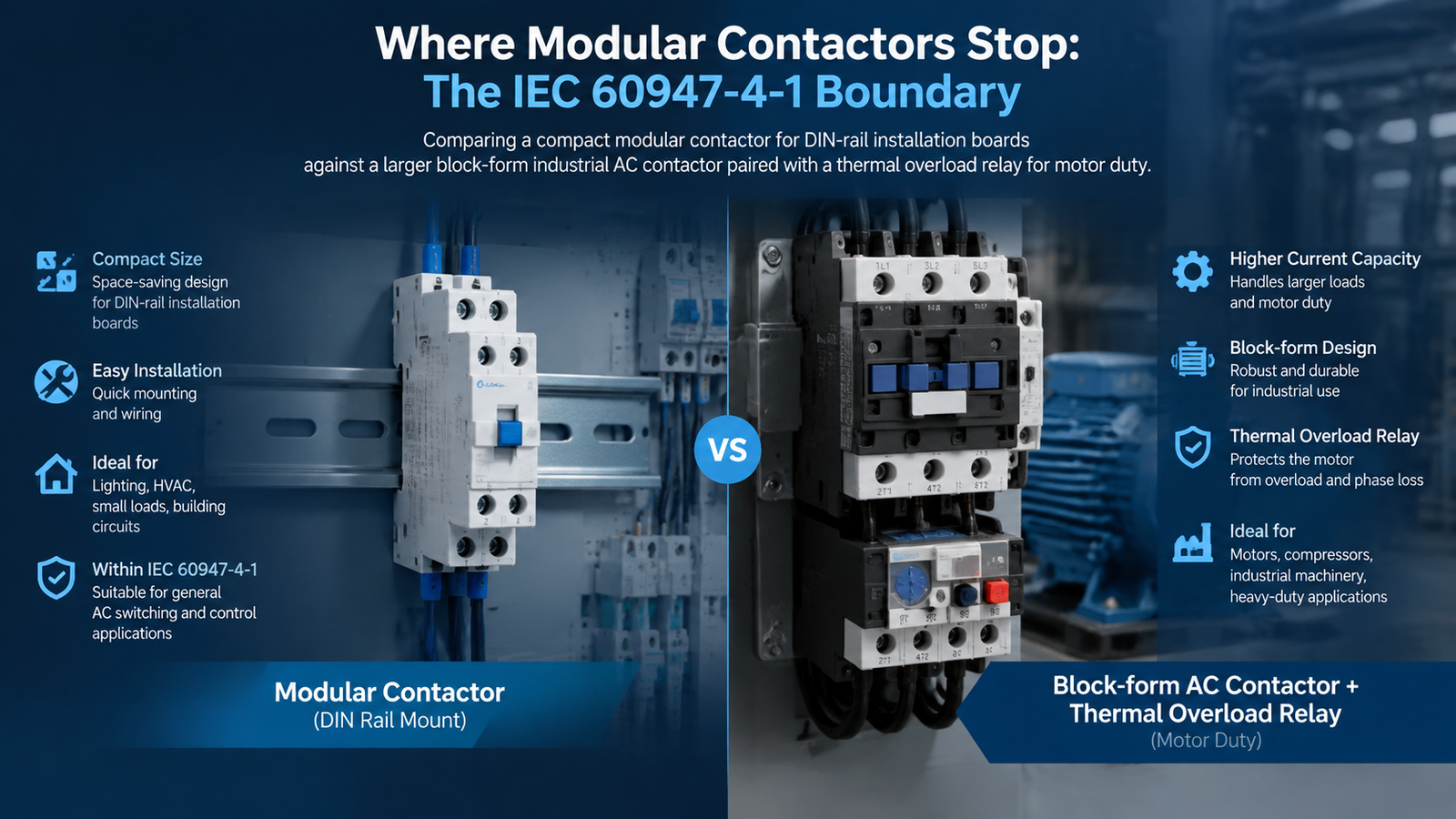
Where Modular Contactors Stop: The IEC 60947-4-1 Boundary
Modular contactors have a defined scope, and it is narrower than the marketing suggests. IEC 61095 applies to electromechanical air-break contactors for household and similar purposes, with main circuits not exceeding 440 V AC between phases, rated operational current not exceeding 63 A in AC-7a and 32 A in the other AC-7 categories, and rated conditional short-circuit current not exceeding 6 kA. Products outside that scope — higher duty, higher ratings, or different switching technologies — fall under IEC 60947-4-1 or another applicable standard.
Dimension
IEC 61095 (modular / installation)
IEC 60947-4-1 (industrial)
Intended application
Household and similar purposes
Industrial motor control and distribution
Voltage scope
Up to 440 V AC between phases
Up to 1000 V AC / 1500 V DC
Current scope
63 A in AC-7a; 32 A in AC-7b, AC-7c, AC-7d
No upper limit
Utilization categories
AC-7a to AC-7d
AC-1 to AC-4, plus DC categories
Conditional short-circuit
Up to 6 kA
Higher, with Type 1 / Type 2 coordination
Typical pairing
DIN-rail board, building automation
Motor starter with overload relay
The practical rule: if the load is resistive or lightly inductive, sits inside a distribution board, stays within the current scope and the installation is not in an occupied space where noise matters, a modular device is the right engineering choice. If the load is a real motor, the rating climbs past the scope boundary, or the duty is severe, you need an industrial contactor and probably an overload relay alongside it.
For motor duty, that usually means a frame rated for AC-3 with an interlock or overload provision. Devices in this class include the CJX2-D (LC1-D) series for compact IEC 60947-4 installations, the CJX2-F series covering the heavier 115 A to 800 A range, and the CJX2-F225 three-phase contactor for 380 V to 660 V motor circuits. Sizing those properly is a different exercise from the seven steps above — the motor-power and AC-3 sizing method applies instead.
Common Selection Mistakes
Mistake
Consequence
Fix
Reading the largest ampere marking
Device is undersized for the actual duty
Start from the utilization category, then the current
Using an AC-7a rating for a motor load
Premature contact wear or welding
Use the published AC-7b rating
Using an AC-7a rating for LED lighting
Contact erosion from inrush within weeks
Use the declared AC-7d rating and driver count limit
Confusing coil voltage with load voltage
Wrong control circuit, or damaged coil
Specify both separately
Treating “2P” as “2NO”
Circuit function is inverted or incomplete
Read pole count and contact state separately
Ignoring controller leakage current
Contactor never releases, load stays live
Compare leakage against coil drop-out threshold
Using the contactor as protection
No fault clearing; serious safety risk
Provide coordinated protective devices
Ignoring ambient and grouping
Overheating and shortened life in a closed board
Apply derating and check spacing
Assuming a family certificate covers your variant
Non-compliant submission
Verify the exact model documentation
Specification Worksheet: Fill This Before You Request a Quote
If several rows in this table are unknown, the project is not ready for a reliable selection and any quotation you receive will be a guess. Complete it first.
Field
Your value
Application and load type
Load supply: AC or DC, voltage, frequency
Load rated current or power
Starting or inrush behaviour
Required utilization category
Number of poles and contact configuration
Coil supply: AC or DC, voltage, frequency
Controller output capability and off-state leakage
Switching operations per hour and per day
Required auxiliary contacts or manual operation
Enclosure ambient, altitude and grouping conditions
Upstream protection and coordination requirements
Destination market and required documentation
결론
The correct modular contactor is not the next ampere size above the load. It is the model whose utilization category, operational voltage, pole configuration, coil supply, switching duty, physical fit and protection coordination all match the application. Start with the load and the category it falls into, work down through the seven specifications, and finish with the exact datasheet. That sequence turns a generic product request into a defensible engineering and purchasing specification — and it is the difference between a contactor that lasts the life of the building and one that is replaced inside a year.
If your application turns out to sit beyond the modular scope — a real motor, a higher rating, or severe duty — browse the AC contactor range or send us the completed worksheet above and we will match it against the right IEC 60947-4-1 frame.
자주 묻는 질문
How do I choose between a 2P and a 4P modular contactor?
Choose the number of conductors the circuit design requires the contactor to switch. Single-phase circuits commonly use one or two switched conductors; three-phase circuits commonly use three, or four where the neutral is intentionally switched for full isolation. Pole count and contact state are separate specifications — a 2P device could be 2NO, 2NC or 1NO+1NC.
Can I use an AC-7a rated contactor for a motor?
Not on the AC-7a rating. Motor loads require the AC-7b rating for that specific model, which is usually lower than the AC-7a figure — the scope limit for AC-7b is 32 A against 63 A for AC-7a. There is no universal conversion factor between categories, so use the manufacturer’s published table for the exact model and voltage.
What is AC-7d and why does it matter for LED lighting?
AC-7d is the utilization category for switching LED lamps and LED control gear, added in the 2023 edition of IEC 61095. LED drivers present a capacitive input, so switch-on produces a steep inrush that can peak many times the steady-state current. Selecting from an AC-7a rating alone will erode contacts quickly. Ask for the declared AC-7d rating and the maximum permitted number of drivers.
Why does my contactor stay energised after the controller switches off?
Almost always control-circuit leakage current. Electronic controllers, dimmers and two-wire sensors can pass a small current even in the off state, and on a low-power coil that is enough to hold the armature in. Check the controller’s off-state leakage against the coil’s drop-out threshold, and confirm the fitted suppression device matches what the datasheet expects.
Do I still need a separate overload relay with a modular contactor?
A contactor only switches; it does not protect. Short-circuit and overload protection come from separate devices such as an MCB, RCBO or motor-protection device, and those must be coordinated so the fault is cleared by the protective device. Modular contactors are normally used without an overload relay, which is one reason they are not suitable for motor duty.
How much should I derate a modular contactor inside a closed distribution board?
Use the manufacturer’s derating curve rather than a rule of thumb. The two inputs that matter most are ambient temperature inside the enclosure and the grouping arrangement of adjacent devices. A board in a plant room can sit 15 to 25 °C above room temperature, and tightly stacked contactors share heat, so the published free-air rating is rarely the usable rating.
Modular and traditional AC contactors are built for different duty. Compare standard, utilization category, coil design, panel space and cost, then use the decision matrix to specify the right one.
A practical thermal overload relay selection guide: match the current range to motor FLA, choose direct, indirect, or CT heating, set the trip class, and pick manual or auto reset.
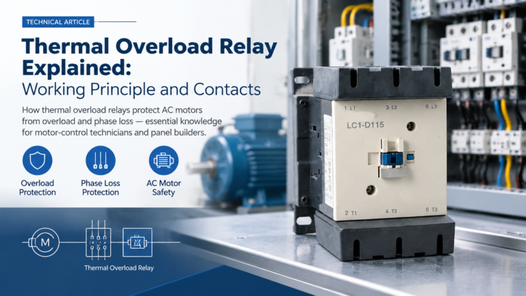
How a thermal overload relay protects motors: the bimetallic working principle, 95-96 NC and 97-98 NO contacts, trip classes, phase-loss protection, and reset modes.