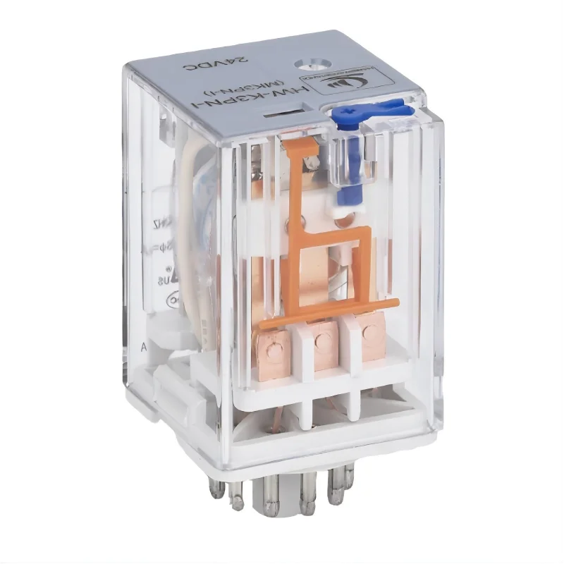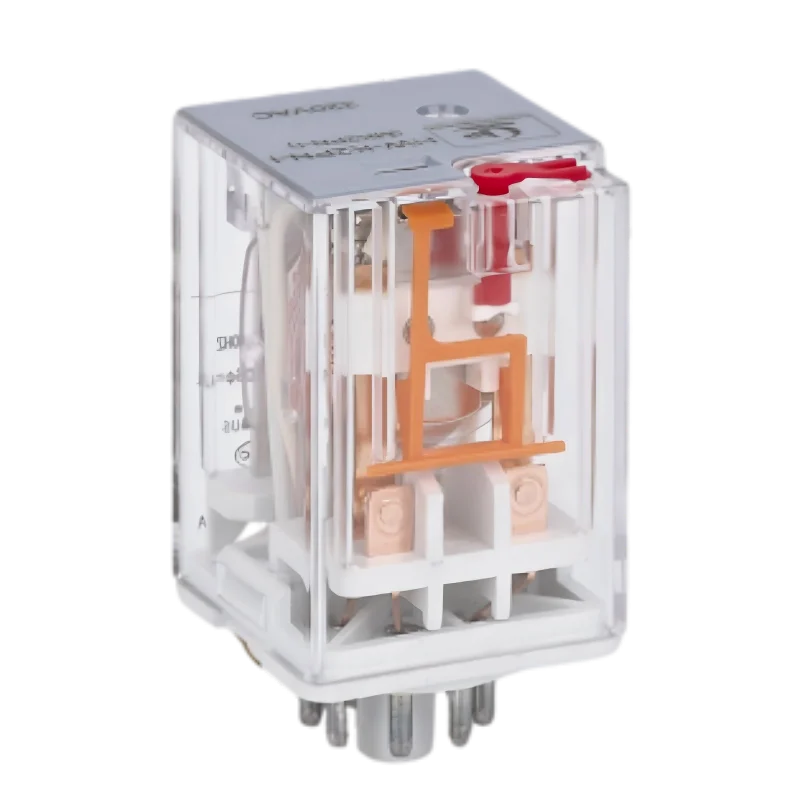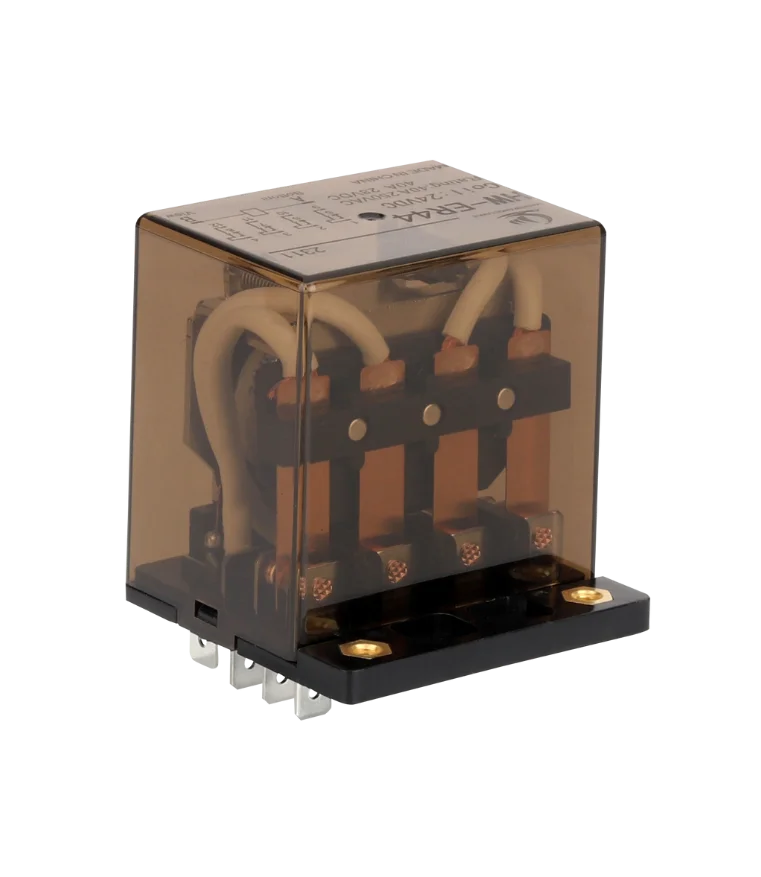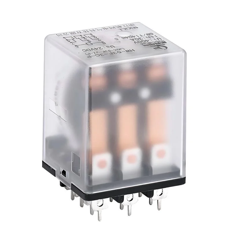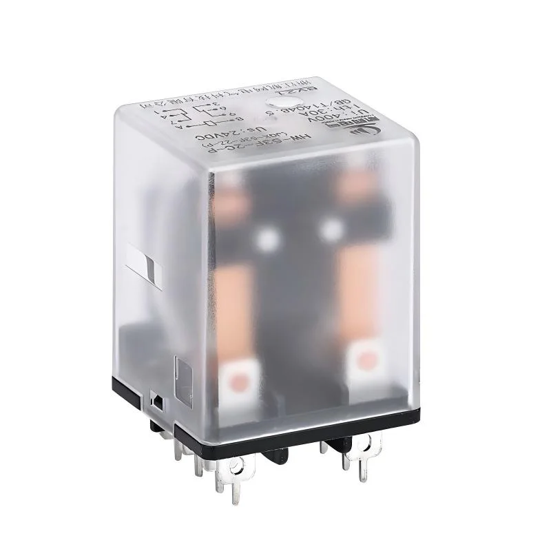
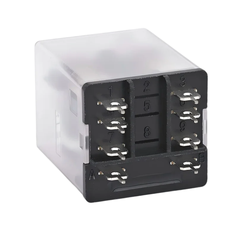
Description
Product Features:
- Robust structure, high impact and vibration resistance, long service life
- Load switching current: 30A
- Direct soldering onto PCB
- 2-group and 3-group contact switching
Model Description
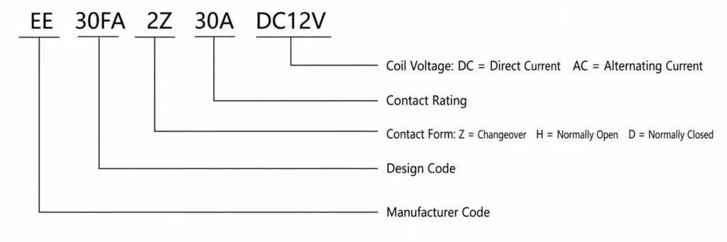
Contact parameters
| Contact type | 2Z,2H,2D |
| Contact load | 30A |
| Maximum switching voltage | 28VDC 30A 240VAC30A |
| Contact Material | Silver alloy |
Contact Type Description
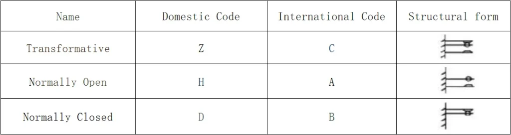
Transformational:In the middle is the moving contact. When the coil isn’t energized, the moving contact is disconnected from one of the stationary contacts and connected to the other. Once the coil is energized, the moving contact moves, causing the previously disconnected contacts to become connected and the previously connected contacts to become disconnected. This achieves the purpose of switching.
Normally Open Type:The contacts are open when the coil is not energized; the contacts close when energized.
Normally Closed Type:When the coil is not energized, the contacts are closed; when energized, the contacts open.
Operating Coils
| Rated voltage | DC12V | DC24V | DC48V | DC110V |
| Rated current (+10%) mA | 150 | 75 | 37.5 | 16.4 |
| Coil resistance (+10%) Ω | 80 | 320 | 1280 | 6720 |
| Rated power consumption W | 1.8W | |||
| Pull-in voltage (maximum) V | Below 75% | |||
| Release voltage (minimum) V | More than 10% | |||
| Allowable Voltage (Maximum) V | Rated voltage x 110% | |||
| Rated voltage | AC12V | AC24V | AC48V | AC220V |
| Rated current (+10%) mA | 208 | 104.2 | 52.1 | 11.4 |
| Coil resistance (+10%) Ω | 20 | 80 | 320 | 6780 |
| Rated power consumption W | 2.5 VA | |||
| Pull-in voltage (maximum) V | Below 80% | |||
| Release voltage (minimum) V | More than 30% | |||
| Allowable Voltage (Maximum) V | Rated voltage x 110% | |||
Product Technical Parameters
| Contact resistance | ≤100mΩ |
| Electrical life | 5×10⁻⁴ times |
| Mechanical life | 1×10⁻⁶ times |
| Coil voltage | DC:6-220V AC:6-380V. |
| Adsorption time | ≤25ms; |
| Release time | ≤15ms. |
| Between the same polarity contacts | 1500VAC/1min(Leakage current 1mA) |
| Between opposite polarity contacts | 2500VAC/1min(Leakage current 1mA) |
| Between contacts and coil | 2500VAC/1min(Leakage current 1mA) |
| Insulation resistance | ≥100MQ(500VDC) |
| Ambient temperature | -25℃~+55℃ |
| Ambient humidity | 35%~80%RH |
| Atmospheric pressure | 86~106KPa |
| Impact resistance | 10G(Sine wave half-pulse: 11ms) |
| Vibration resistance | 10-55Hz Double amplitude:1.5mm |
| Size | 38×36×56.5mm |
| Weight | Approximately 77g |
Product Dimensions and Installation Methods
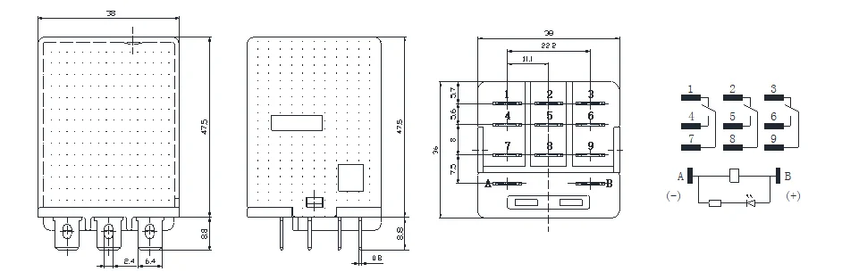
Selection Guidelines
Unless otherwise specified, all load currents indicated on the relay housings refer to resistive loads. At the rated switching voltage, the allowable current for inductive loads should not exceed 30% of the rated resistive load current. For motor loads, the allowable current should not exceed 20% of the rated resistive load current. For lighting loads, it should not exceed 10%. For capacitive loads, it should not exceed 5%. To ensure reliable operation of the product, it is recommended that the contact load current not exceed 60%–70% of the steady-state current at the rated load.
| Nature of the load | Inrush current |
| Resistive load | 1 times the steady-state current |
| Sodium lamp load | 1-3 times the steady-state current |
| Mercury lamp load | 3 times the steady-state current |
| Inductive load | 3-5 times the steady-state current |
| Motor load | 3-5 times the steady-state current |
| Transformer load | 3-5 times the steady-state current |
| Incandescent lamp load | 3-5 times the steady-state current |
| Capacitive load | 3-5 times the steady-state current |
Request Quote
Tell us your specifications, quantity, or application scenario and we will reply with a tailored quote.