
Quick answer: AC-12 to AC-15 are control-circuit categories (IEC 60947-5-1) for auxiliary contacts and control relays: AC-12 make 1× / break 1× at cos φ 0.9, AC-13 2× / 1× at 0.65, AC-14 6× / 1× at 0.3 for loads up to 72 VA, AC-15 10× / 1× at 0.3 above 72 VA. AC-20 to AC-23 are main-circuit categories (IEC 60947-3) for switches and switch-disconnectors: AC-20 no-load isolation, AC-21 make 1.5× / break 1.5× at 0.95, AC-22 3× / 3× at 0.65, AC-23 make 10× / break 8× at 0.45 for motor and other highly inductive loads. An AC-23 switch-disconnector is not a substitute for an AC-3 contactor — the numbers look alike but the endurance test behind them is different.
Contactor utilisation categories are usually taught as a single list running AC-1, AC-2, AC-3, AC-4, and then everyone stops. That leaves the rest of the alphabet unexplained: the numbers above 10 that appear on switch-disconnectors, on isolators, on auxiliary contact blocks and on terminal blocks, and that buyers compare with motor contactor ratings as if they were the same thing.
They are not. Three different IEC standards define these categories, each with its own test regime, and the whole confusion around “AC-23 versus AC-3” comes from reading a number out of one standard against a number from another. This page lays out both families, the make and break multiples, what each category actually tests, and where each one belongs on a real panel.
Three standards, three families
Before the numbers, the map. Every utilisation category you will meet on a low-voltage switching device belongs to one of three documents:
| Standard | Device | Categories | Question it answers |
|---|---|---|---|
| IEC 60947-4-1 | Contactors and motor starters | AC-1 to AC-8b, DC-1 to DC-6 | Can this contactor start and stop this load, and for how many operations? |
| IEC 60947-5-1 | Control-circuit devices, auxiliary contacts | AC-12 to AC-15, DC-12 to DC-14 | Can this auxiliary contact switch this control load? |
| IEC 60947-3 | Switches, disconnectors, switch-disconnectors, fuse combination units | AC-20 to AC-23, DC-20 to DC-23 | Can this isolator make and break this load, and how often? |
That is why the sequence jumps from 8 to 12 to 20. The gaps are not missing categories; they are different documents. AC-9 to AC-11 and DC-7 to DC-11 are obsolete or reserved designations, and the AC-12 to AC-15 block once ran as AC-11 and its sub-grades before the current structure was adopted.
The contactor family itself — AC-1 through AC-4 — is covered in AC-1 to AC-4 utilization categories, and the newer members (AC-6a, AC-6b, AC-7a, AC-7b) in the transformer, capacitor and appliance articles linked from it.
AC-12 to AC-15: what an auxiliary contact can really switch
These four categories exist because auxiliary contacts are frequently asked to switch things far more demanding than a pilot light. The test conditions are defined at 1.1 × rated operational voltage for the first 50 operations, with the load set at rated voltage, then at rated voltage for the remaining 6,000 cycles.
| Category | Typical load | Make | Break | cos φ | Where you meet it |
|---|---|---|---|---|---|
| AC-12 | Resistive loads and solid-state loads with optocoupler isolation | 1 × Ie | 1 × Ie | 0.9 | PLC digital inputs, indication lamps, resistive heaters on control circuits |
| AC-13 | Solid-state loads with transformer isolation | 2 × Ie | 1 × Ie | 0.65 | Isolated signal circuits, small transformers feeding electronics |
| AC-14 | Small electromagnetic loads, ≤ 72 VA holding power | 6 × Ie | 1 × Ie | 0.3 | Miniature relays, small contactor coils, solenoid valves |
| AC-15 | Electromagnetic loads above 72 VA | 10 × Ie | 1 × Ie | 0.3 | Contactor and large relay coils, the default auxiliary contact rating |
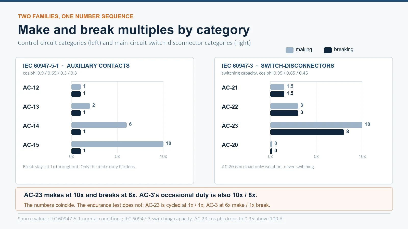
Two features of this table explain most field failures. First, the make multiple rises sharply as the load gets more inductive — from 1 × to 10 × — while the break multiple stays at 1 × for all four. The 72 VA line between AC-14 and AC-15 is not arbitrary: it is the point where the coil’s stored magnetic energy at the instant of break becomes enough to sustain an arc across a small auxiliary gap.
Second, the power factor column tells you what the contact is really seeing. At cos φ 0.3 the current lags the voltage by about 72 degrees, so the contact opens near the current peak while the voltage across the gap is already rising towards its maximum. That phase relationship is why an AC-15 rating at a given voltage is much lower than an AC-12 rating at the same voltage, and why the auxiliary contact that switches the coil is always the one that pits.
Auxiliary contact blocks are usually published with both an AC-15 and a DC-13 rating, because a contactor coil may be either. Do not assume the AC-15 figure covers a DC coil: at 220 V DC an AC-15 rated block may be limited to a fraction of its AC current, because a direct current has no zero crossing to extinguish the arc. The comparison is in AC-15 vs DC-13 auxiliary contact ratings.
AC-20 to AC-23: what a switch-disconnector is allowed to break
The main-circuit family is the one buyers use to compare isolators with contactors, and the one most often misread. These categories are defined in IEC 60947-3, and the same category number appears twice in the standard with two different meanings: once as an endurance condition and once as a switching capacity verification.
| Category | Typical application | Endurance make / break | cos φ | Switching capacity make / break | cos φ |
|---|---|---|---|---|---|
| AC-20 | Connecting and disconnecting under no load | No load | — | No load | — |
| AC-21 | Resistive loads, including moderate overloads | 1 × / 1 × | 0.95 | 1.5 × / 1.5 × | 0.95 |
| AC-22 | Mixed resistive and inductive loads, including moderate overloads | 1 × / 1 × | 0.80 | 3 × / 3 × | 0.65 |
| AC-23 | Motor loads or other highly inductive loads | 1 × / 1 × | 0.65 | 10 × / 8 × | 0.45 up to 100 A, 0.35 above |
Read the two right-hand columns separately, because they answer different questions. The endurance columns describe the load the device is cycled at to earn its mechanical and electrical life figure — deliberately light, one times rated current, because a switch-disconnector is expected to spend most of its life carrying current and only occasionally breaking it. The switching capacity columns describe the abnormal event it must survive — the ten-times make and eight-times break that a motor circuit can present.
IEC 60947-3 also splits each category into A and B suffixes. A means the device is intended for frequent operation and carries the higher number of test cycles; B means infrequent operation, typically isolation and maintenance, with a much lower cycle count. A switch marked AC-23A and one marked AC-23B have the same make and break capability but very different expected lives. When a quotation says only “AC-23”, ask which suffix.
Why AC-23 is not AC-3
Here is the trap. An AC-23 switch-disconnector’s switching capacity is 10 × make and 8 × break. An AC-3 contactor’s occasional duty capacity is also 10 × make and 8 × break at cos φ 0.45 for frames up to 100 A. The numbers match, so buyers conclude the devices are interchangeable. They are not, for three reasons.
- The endurance condition is different. AC-3 endurance is verified at 6 × Ie make and 1 × Ie break, at cos φ 0.65 for frames up to 17 A and 0.35 above. AC-23 endurance is verified at 1 × Ie make and 1 × Ie break at cos φ 0.65. A switch earns its AC-23 life without ever breaking a starting current; a contactor earns its AC-3 life by making six times rated current on every single cycle.
- The cycle counts are different. AC-3 ratings are quoted against a declared electrical life measured in hundreds of thousands of operations for small frames. An AC-23B switch may be tested for a few thousand. Same numbers on the make column, wildly different duty behind them.
- The device has a different job. A switch-disconnector provides isolation and visible break. A contactor provides frequent, remote, high-cycle switching. Putting an AC-23 isolator in the contactor position gives you a device that can survive a motor start but is not built to do it ten times an hour.
The practical rule: an AC-23 rating on a switch-disconnector means “safe to operate on a motor circuit”, not “rated for motor starting duty”. If the device is going to start and stop the motor, it needs an AC-3 contactor rating from IEC 60947-4-1. The distinction between switching duty and protection duty is set out further in contactor vs circuit breaker.
The make/break asymmetry that misleads everyone
Across both families, the make multiple is generally much larger than the break multiple — 10 × versus 1 × for AC-15, 10 × versus 8 × for AC-23, 6 × versus 1 × for AC-3. This is not an oversight in the standards; it reflects what the two events do to a contact.
On make, the contacts approach each other across a gap that is breaking down. The arc is short-lived but the current is limited only by the circuit impedance, and the first contact is a point contact on a microscopically small area, so the local energy density is enormous. Pre-strike bouncing — the contacts touch, bounce apart, re-strike, several times within a millisecond — multiplies the number of arc roots on the same spot and is the main mechanism behind contact welding.
On break, the arc is drawn out as the contacts separate. Its duration depends on how quickly the arc chute can split and cool it, and its severity depends on the current at the instant of separation and the recovery voltage across the gap. For a resistive load the current and voltage are nearly in phase, so the arc is drawn at a favourable moment and extinguishes quickly. For an inductive load at cos φ 0.3 the current peak coincides with a rising recovery voltage, and the arc is both longer and hotter.
That is the physical reason the AC-12 to AC-15 make multiple climbs from 1 × to 10 × as the power factor falls from 0.9 to 0.3, while the break multiple stays at 1 ×: at a 1 × break the standard is not asking the contact to interrupt anything unusual, only to survive the make.
Which number applies to your circuit
Reading a datasheet with six category columns is easier with a decision sequence:
| What the device does | Category to read | Standard |
|---|---|---|
| Starts and stops a cage motor in normal service | AC-3 | IEC 60947-4-1 |
| Plugs, jogs or inches a cage motor | AC-4 | IEC 60947-4-1 |
| Starts and stops a wound-rotor motor | AC-2 | IEC 60947-4-1 |
| Switches a resistive heater | AC-1 | IEC 60947-4-1 |
| Switches a transformer or capacitor bank | AC-6a / AC-6b | IEC 60947-4-1 |
| Switches lighting | AC-5a / AC-5b, or AC-7a | IEC 60947-4-1 |
| Auxiliary contact switching a contactor coil above 72 VA | AC-15 | IEC 60947-5-1 |
| Auxiliary contact switching a small relay coil up to 72 VA | AC-14 | IEC 60947-5-1 |
| Auxiliary contact switching a PLC input | AC-12 | IEC 60947-5-1 |
| Isolator that only ever opens off-load | AC-20 | IEC 60947-3 |
| Isolator on a resistive distribution circuit | AC-21 or AC-22 | IEC 60947-3 |
| Isolator on a motor feeder, opened occasionally | AC-23 (usually B) | IEC 60947-3 |
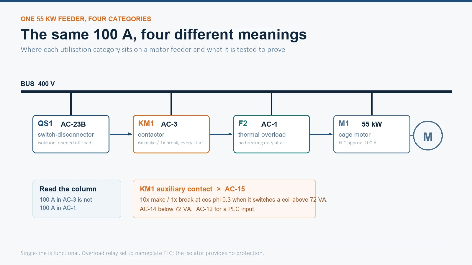
Worked example: a 55 kW motor feeder
A 55 kW, 400 V cage motor with a full-load current of about 100 A, started direct-on-line and isolated for maintenance only.
- Contactor. Read the AC-3 column at 400 V. The frame must be rated at or above 100 A in that column — not in the AC-1 column, which will show a much larger number for the same frame and is the single most common sizing error. The make duty is 6 × 100 A = 600 A on every start, and the declared electrical life at that duty is the number that predicts replacement intervals.
- Isolator. Read the AC-23 column at 400 V. A 100 A AC-23B switch is adequate for maintenance isolation, because its switching capacity is verified at 10 × make and 8 × break — it can survive being opened on a locked rotor, which is the abnormal case the standard is protecting against.
- Overload relay. Set to the motor’s nameplate current, in the contactor’s load path, not in the isolator. The isolator provides no protection of any kind.
- Control contact. The auxiliary contact that holds the contactor in is switching a coil of perhaps 10 VA, which is AC-14 territory, but it will be rated AC-15 because that is the default block rating. The auxiliary contact that switches the coil of a second contactor in an interlock is doing the same job at a higher inrush and must be checked against AC-15 at the control voltage.
Notice that the same 100 A appears four times with four different meanings. That is the whole point of the category system: the ampere rating is meaningless without the category attached to it.
Where these categories show up in a quotation
In practice the categories appear in three places, and each has a habit of being omitted:
On a switch-disconnector datasheet, look for a table with AC-20 through AC-23 down the side and two blocks of columns across the top. If only one block is given, the manufacturer is quoting switching capacity and not endurance — which is acceptable for isolation duty but tells you nothing about life under load.
On an auxiliary contact block, the AC-15 figure is usually quoted at a reference voltage, often 220/240 V, with lower currents at 380/440 V. Always read the value at your control voltage. A block rated 6 A AC-15 at 220 V may be 3 A at 440 V and 1 A at 690 V.
On a terminal or busbar, categories do not appear at all, which is why terminal current ratings and device category ratings are so often mixed up. A terminal rated 100 A continuous has no breaking capability whatsoever.
FAQ
What is the difference between AC-3 and AC-23?
AC-3 is a contactor category in IEC 60947-4-1 for squirrel-cage motor starting and stopping during running, with endurance verified at 6 × make and 1 × break. AC-23 is a switch-disconnector category in IEC 60947-3 for motor and other highly inductive loads, with endurance verified at 1 × make and 1 × break and a switching capacity of 10 × make and 8 × break. The switching capacity numbers coincide, which is why the two are confused, but the endurance duty behind them is entirely different.
What does AC-15 mean on an auxiliary contact?
AC-15 is the control-circuit category for switching electromagnetic loads drawing more than 72 VA with the electromagnet closed — in practice, contactor and large relay coils. It requires a making capacity of 10 times rated current and a breaking capacity of 1 times, at a power factor of 0.3.
Why is AC-14 limited to 72 VA?
72 VA is the point at which the stored magnetic energy in the coil at the instant of break becomes sufficient to sustain an arc across a typical auxiliary contact gap. Below it the contact only has to survive the make, hence the 6 × make and 1 × break. Above it the break itself becomes the limiting event, and the category moves to AC-15 with a 10 × make requirement.
Can I use an AC-23 isolator as a motor contactor?
No, not for starting duty. It can survive a motor start — its switching capacity is verified at 10 × make and 8 × break — but its endurance was never demonstrated at 6 × Ie make per cycle, and its cycle count reflects occasional operation. Use an AC-3 rated contactor for switching and an AC-23 isolator for isolation.
What do the A and B suffixes on AC-23 mean?
A denotes a device intended for frequent operation with the higher test cycle count; B denotes infrequent operation, typically isolation and maintenance, with a lower count. Both have the same making and breaking capacity, so a quotation that says only “AC-23” has not told you which one you are buying.
Is AC-20 a real rating?
Yes. AC-20 means the device is rated to connect and disconnect only under no-load conditions, which is exactly what an isolator used purely for isolation does. It is a legitimate rating for a maintenance isolator and an inadequate one for anything that will be opened on load.
Which category applies to a DC coil?
None of the AC categories. A DC coil is switched under DC-13 (electromagnetic loads, time constant defined by 6 × P) or DC-12 for resistive and optocoupler-isolated loads. An AC-15 rating does not transfer to a DC control circuit, because a direct current has no zero crossing to help extinguish the arc.
What to do next
Three steps. Identify the standard the device is tested to, because that fixes which family of categories applies. Identify the load, because that fixes the category inside the family. Then read the value at your actual operating voltage and, for a switch-disconnector, confirm whether the quoted figure is switching capacity or endurance.
For motor switching duty in the AC-3 and AC-4 range, the 3TF series AC contactor is rated by utilisation category at each operating voltage, and the framework behind those columns is set out in IEC 60947-4-1 explained. If you send the load type, the operating voltage and the operations per hour, we will tell you which category column to read and what frame it lands on — rather than quoting an ampere figure that means four different things.