Aircraft vs Aerospace vs Aviation Connectors: What Buyers Actually Mean
What aircraft, aerospace and aviation connectors actually mean in procurement, which standards govern each, and where industrial circular connectors fit.
Read More
Of all the circular connector searches we see in inquiry logs, “4 pin aviation connector wiring diagram” is the one with the clearest intent: someone has a 4-pin plug in one hand, a cable in the other, and needs to know which conductor goes where — and why the shield matters. This guide covers the pin functions, the soldering order, the 360° shield termination, and the grounding mistakes that turn a perfectly good sensor cable into an intermittent fault.
The advice applies to any M12/M16-class threaded circular connector — GX12, GX16, LD and SD series — because the 4-pin internal layout and the wiring discipline are the same across all of them. Part numbers change; the pin logic does not.
| Pin (centre = 1) | Power application | Signal application | Conductor size (typ.) |
|---|---|---|---|
| Pin 1 (centre) | +V supply (24 V DC typical) | Signal A / RS-485 A | 0.5–1.0 mm² |
| Pin 2 (inner ring) | 0 V return | Signal B / RS-485 B | 0.5–1.0 mm² |
| Pin 3 (inner ring) | Shield / drain | Shield / drain | Drain wire or braid tail |
| Pin 4 (inner ring) | PE / chassis earth | Signal C or 0 V reference | 0.75–1.5 mm² |
Two conventions dominate in practice. The power convention assigns supply, return, shield and protective earth — used for sensors, small actuators and light fittings. The signal convention assigns a differential pair plus shield plus reference — used for RS-485/Modbus runs, encoders and instrumentation. Before you solder, confirm which convention the equipment at both ends expects; the pin metalwork is identical, only your assignment differs.
One warning that saves rewiring: never assume pin 1 is positive on a connector that was supplied with a device. Some manufacturers mirror the pinout on the cable side so that the same pin number faces the same conductor at both ends. Check the device’s datasheet pin table, or buzz the pins out with a meter, before the first solder joint goes on.
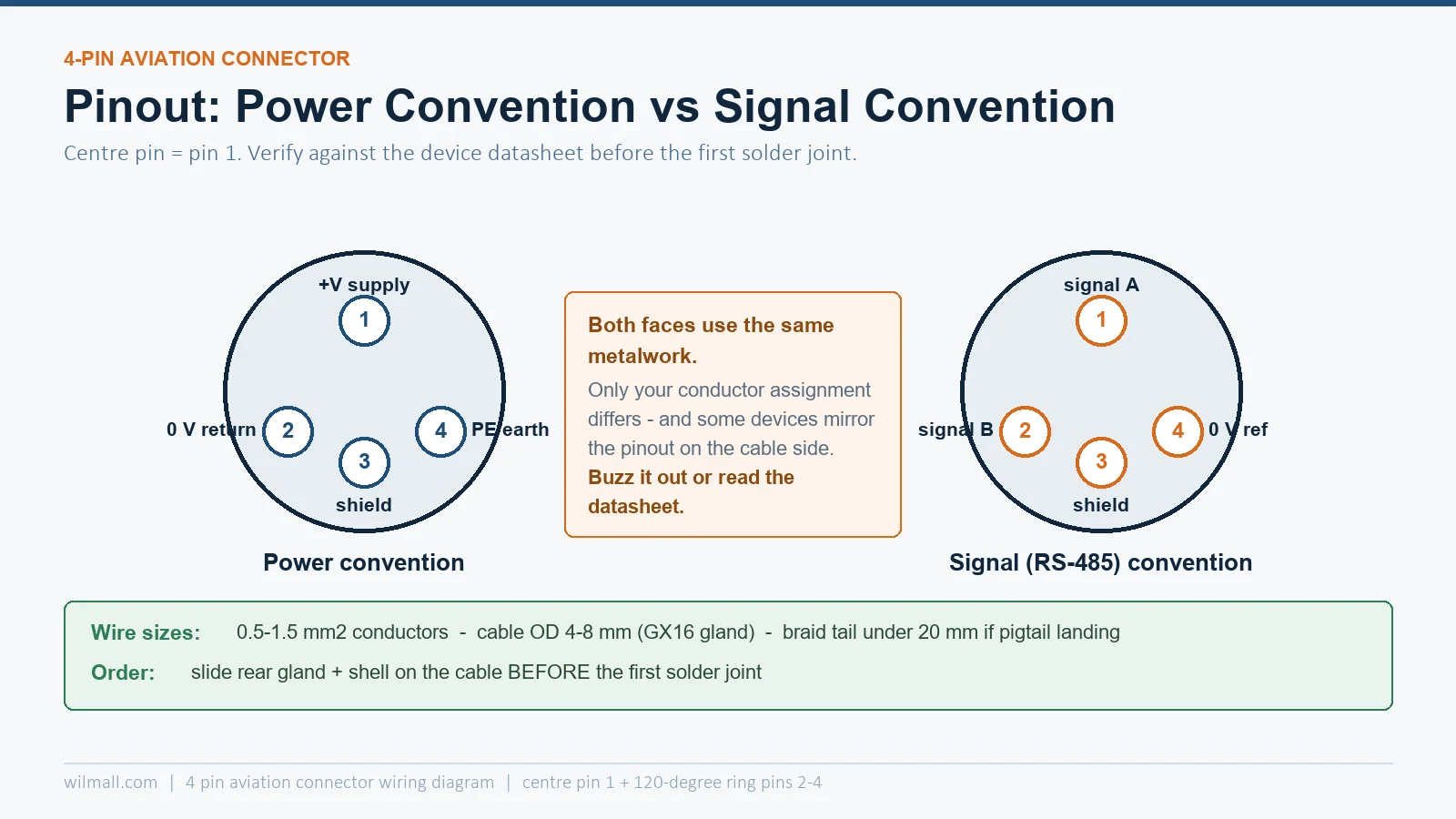 ” />
A 4-pin circular connector arranges its contacts as one centre pin plus three pins on an inner ring, spaced 120° apart. The centre pin is almost always assigned first because it is the shortest connection path and the most mechanically protected — that is where the supply or the first signal leg goes. The three ring pins follow clockwise when viewed from the solder side of most common series, but this orientation is not standardised between brands, which is exactly why the datasheet check matters.
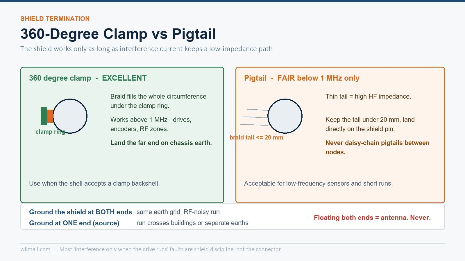
The shielding discussion is where most field-wired 4-pin connections go wrong. Electromagnetic shielding works by giving interference currents a continuous low-impedance path around the conductor. The moment that path narrows to a thin pigtail wire, the impedance at high frequencies rises and the shield stops working above roughly 1 MHz — exactly the range where drives, switching supplies and radio services live.
| Method | HF performance | Field-practicality | Use when |
|---|---|---|---|
| 360° clamp to connector shell (EMI backshell or clamp ring) | Excellent | Needs the right shell/accessories | Drives, encoders, instrumentation — any run near a VFD |
| Short pigtail to shield pin | Fair below 1 MHz | Always possible | Low-frequency sensor signals, short runs |
| Long pigtail, daisy-chained | Poor | Common bad habit | Never — this is the fault generator |
| Shield cut off entirely | None | — | Only for short, benign digital I/O in quiet cabinets |
The practical hierarchy: if the connector family supports a clamp-type backshell (many LD/SD moulded shells and metal GX shells with the right accessory do), terminate the braid 360° under the clamp. If not, keep the pigtail as short as physically possible — under 20 mm of exposed drain, stripped and landed directly on the shield pin — and land the other end of the shield on clean chassis earth, not on the electronics 0 V.
The classic argument. Grounding the shield at both ends gives the best HF performance but invites a ground loop if there is a potential difference between the two earths. Grounding one end (source side) eliminates the loop but sacrifices some high-frequency shielding. The working rules:
For screw-terminal versions of the same connectors — common on the LD16 series aviation plug — skip the soldering steps: strip 6 mm, insert, torque the screw. The shield discipline and the pin-assignment checks stay identical, which is why screw-terminal bodies are worth specifying for anything a maintenance team will rewire.
 ” />
| Symptom | Likely cause | Check |
|---|---|---|
| Signal works when still, fails when the cable moves | Cold solder joint or strain on the joints | Flex the cable at the gland while watching the signal |
| Intermittent faults only when a drive runs nearby | Pigtail shield or floating shield | Inspect the shield landing; convert to 360° clamp if possible |
| Ground-fault breaker trips when connector is mated | PE conductor landed on a supply pin | Buzz out against the datasheet; check for insulation damage in the cup area |
| Corroded pins after months outdoors | Unsealed connector in a wet location | Move to an IP-rated sealed series; both mated and unmated states must seal |
| RS-485 network marginal, errors cluster at one node | Shield grounded at both ends across different earths | Lift one shield end; measure the loop current that disappears |
Most of these trace back to two root causes: mechanical strain that should have been taken by the gland, and shield discipline that was skipped because “it worked without it” on the bench. Both are cheaper to prevent than to diagnose.
Once the wiring plan is right, the connector choice is mostly about environment and serviceability. Indoor dry panel, bench or machine-internal: a metal GX16 in 4-pin is the default. Outdoor or washdown-adjacent, where the connection may sit unmated between shifts: a sealed series such as the SD16 aviation cable connectors with caps on both halves keeps water out of the contacts. Compact sensor heads and tight enclosures take the smaller SD13 footprint with the same 4-pin logic. For a full comparison of sizes and pin counts across the families, see our GX16 vs GX12 vs LD16 size and pin chart, and for the wider series overview the aviation connector category lists every model we stock with drawings.
There is no universal standard. The common power convention assigns pin 1 (centre) to +V, but device manufacturers sometimes mirror the pinout on cable-side connectors. Always verify against the datasheet or buzz out the connector before soldering.
Both exist. Pin 3 (shield pin) is the standard connection point; a 360° clamp to the shell is better where the connector and backshell support it. In either case, land the shield’s far end on chassis earth per the one-end/both-ends rules above.
Not recommended. Standard GX16 contacts and their pin spacing are not designed or certified for mains voltage in the clearance/creepage sense that a proper appliance inlet requires. Use a rated mains connector or a dedicated industrial rectangular connector for line voltage.
0.5–1.5 mm² for the common solder-cup and screw-terminal versions, with the 4–8 mm overall cable diameter range set by the rear gland. Check the specific supplier’s drawing — cup sizes vary slightly between brands.
Almost always a shielding problem: a long pigtail, a shield floating at one end, or signal conductors laid in the same bundle as the motor cable. Fix the 360° shield termination and separate the power and signal looms.