Contactor Coil Test: Resistance, Pickup and Drop-out Voltage
Published: Author: Lisa
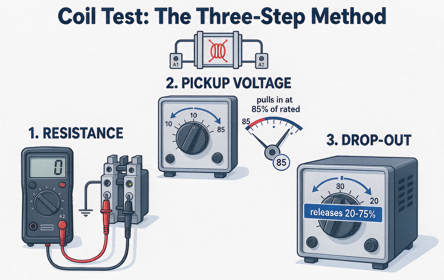
A contactor coil test answers one of three questions: is the coil electrically sound, will it pull in reliably on this control supply, and why did the last one burn? A multimeter across A1 and A2 gives you the first answer in seconds — but only if you know what the reading should be, and the datasheet rarely prints it.
This guide gives the resistance reference method, the IEC pickup and drop-out voltage windows, the inrush-vs-sealed current distinction that separates AC coil behavior from DC, and the five root causes that show up as “burnt coil” when the coil was only the messenger. It assumes you already know which coil voltage you have; the marking systems (24 V, 110 V, 220 V, 380 V, and the 50/60 Hz codes) are decoded in the contactor coil voltage guide.
Quick Answer: The Three Tests and What Each Tells You
Test
Instrument
Expected result
Failure signature
Coil resistance (cold, de-energized)
Multimeter, ohms range, across A1–A2
Matches the manufacturer’s coil table for that voltage and frame; same-code coils interchangeable within a family
Open circuit = burnout or broken termination; far below table = shorted turns; far above = wrong coil or corroded termination
Pickup voltage (pull-in)
Adjustable control supply, voltmeter at A1–A2
Pulls in reliably at ≤ 85% of rated voltage (IEC 60947-4-1 window: 85–110%)
Needs > 85% to seat, or chatters while seating: weak supply, sticky mechanism, or partially shorted coil
Drop-out voltage (release)
Reduce supply slowly from sealed-in
Releases between 20% and 75% of rated voltage
Releases above 75%: mechanism worn or spring fatigued; holds below 20%: remanence risk — armature may not drop on real power loss
The resistance test is static screening. The pickup and drop-out tests are dynamic truth: they measure the coil together with the mechanism it moves, which is why a coil that reads perfectly can still fail the pull-in test on a dirty pole face.
Test One: Coil Resistance and the Reference Table
Coil resistance varies by voltage and frame, but the scaling is systematic: a 380 V coil has roughly 250× the resistance of a 24 V coil of the same sealed power. If you record resistance per coil type at commissioning, every future reading has a reference. Typical orders of magnitude for a mid-size IEC frame (sealed power ≈ 10 VA):
Coil rated voltage
Typical cold resistance (order of magnitude)
Typical sealed current
24 V 50/60 Hz
≈ 5–15 Ω
≈ 0.4 A
110 V 50/60 Hz
≈ 100–300 Ω
≈ 0.09 A
220–240 V 50/60 Hz
≈ 400–1,200 Ω
≈ 0.045 A
380–400 V 50/60 Hz
≈ 1,500–4,000 Ω
≈ 0.026 A
Interpretation rules:
Exact values are coil-code specific. The table above is a sanity band, not a datasheet. Compare against the same manufacturer’s coil table or against the sister contactor in the same panel — the identical device next to it is the best reference instrument you own.
Shorted turns read “normal-ish” cold. A few shorted turns may only drop resistance by 10–20%, inside the band. The symptom appears dynamically instead: the coil pulls in weakly, hums louder than its twin, or runs hot at the same voltage. If resistance is borderline AND behavior is wrong, trust the behavior.
Temperature shifts the reading. Copper resistance rises ~0.4% per °C; a coil measured hot reads 15–20% higher than cold. Baseline cold readings against cold.
AC vs DC coils are not comparable. A DC (or rectified/economized) coil has far higher resistance for the same voltage and shows a two-stage pickup (large inrush through both windings, then the economy contact cuts in). If the device has a rectifier module or three coil terminals, it is not a plain AC coil — test it as the manufacturer describes, not with the generic method.
Test Two: Pickup Voltage — the 85% Window
IEC 60947-4-1 requires the contactor to pull in and seat completely between 85% and 110% of rated control voltage (at reference conditions). The window exists because real control buses sag: a 220 V coil must seat on 187 V at the coil terminals, not at the panel feeder.
Field method with an adjustable supply (or a variac on AC):
Connect the voltmeter directly at A1–A2 — the voltage at the coil is what matters; line drop in the control wiring is part of the answer.
Ramp from zero and record the voltage where the armature fully seats and the main contacts close (verify with a continuity check across L1–T1, not by ear).
Requirement: full seating at ≤ 85% rated. Marginal seating above that = failed pull-in margin.
Then hold at rated voltage and listen: a correctly seated armature is nearly silent. Buzz at full voltage means dirt or wear on the pole faces, not necessarily a coil problem — the hum diagnostics are detailed in the contactor troubleshooting guide.
Why a coil can fail this test while resistance reads fine:
Mechanical friction: a gummed or worn mechanism needs more magnet force; the coil may be perfectly capable in a healthy frame.
Pole-face contamination: an air gap at seating raises reluctance and drops the holding force — the coil works harder, runs hotter, and chatters.
Partially shorted turns: less effective ampere-turns at the same voltage.
Supply is the problem, not the coil: long control runs, undersized transformers, or brownouts during motor starting pull the coil-terminal voltage below the window. Measure under the real fault condition — the coil-terminal voltage during an actual start attempt is the most diagnostic single number in the whole panel.
Test Three: Drop-out Voltage — the Safety Margin Nobody Checks
Ramp the supply down from full and record where the armature releases. IEC expects release between roughly 20% and 75% of rated voltage. Two failure directions, opposite risks:
Drop-out behavior
Risk
Likely cause
Releases above 75%
Nuisance drop-out on routine sags — process stops, contact wear from needless operations
Weak springs, worn mechanism, or wrong coil in frame
Holds below 20% / will not release at zero applied voltage
Safety: the load stays energized after an E-stop command
Remanence (residual magnetism in a degraded core), welded contacts, or mechanical sticking
The second row is the dangerous one. If a contactor does not drop out when the coil is de-energized, first check whether the contacts are welded (continuity across the main poles with the coil dead — if yes, this is a fault-event contactor, replace the device as covered in the contact reset guide). If the contacts are open but the armature stays stuck, the core faces are remanent or damaged — also a replace, not a repair.
This drop-out margin is exactly why surge suppression choices matter: an RC snubber or MOV across the coil keeps the armature from chattering but can extend release time; a flyback diode on a DC coil extends it dramatically. The trade-offs are quantified in the surge suppressor selection guide.
Inrush vs Sealed: Why an AC Coil Draws 5–10× More to Pull In
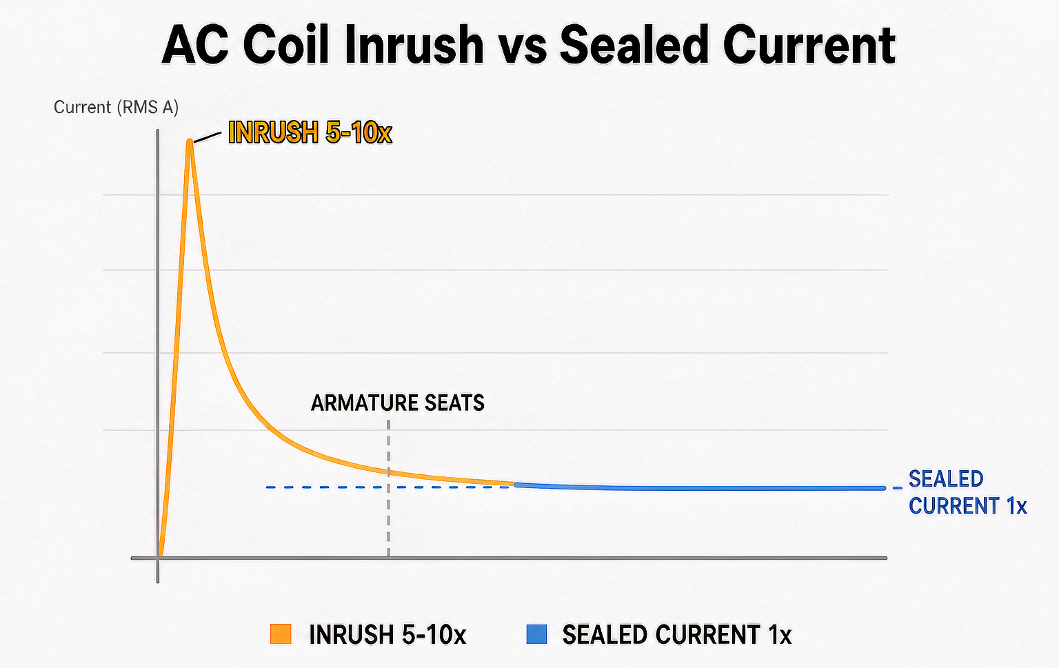
An AC coil’s impedance depends on the armature position. Open armature: low inductance, high current — the inrush. Seated armature: the magnetic circuit closes, inductance rises, current falls to the sealed value. Practically, inrush is 5–10× the sealed current for a few tens of milliseconds.
Three consequences that show up as “coil problems”:
Sizing the control transformer: it must carry the inrush of every coil that can pull in simultaneously, or the voltage sags below the 85% window exactly when you need pull-in — the classic “three contactors at once” nuisance failure.
Rapid cycling kills AC coils: every start is an inrush event and a thermal event. A contactor hammering on a chattering loop is cooking itself at 5–10× sealed current. This is the most common mechanism behind “the coil keeps burning” reports.
DC coils behave opposite: flat current, no inrush penalty, much longer life in high-cycle duty — one reason energized DC control buses exist in high-cycle machinery.
Why Coils Actually Burn: Five Root Causes
Root cause
Evidence on the failed coil / panel
Fix the cause, not just the coil
Sustained undervoltage / chatter
Scorched windings, buzz reported before failure, control bus sags during starts
Fix the supply or move to the correct coil voltage; verify pickup margin at the coil terminals
Overvoltage
Burnout without chatter history; measured coil-terminal voltage > 110%
Check control transformer taps and regulator settings
Mechanical binding / pole-face contamination
Armature faces dirty or worn; coil burns even though it “tests fine”
Clean or replace the mechanism; the coil is a symptom
Wrong voltage coil installed
Resistance wildly off the table for the applied voltage; failure within hours of a “replacement”
Match coil code to control supply; record in the panel schedule
Switching-transient damage
Termination or interturn insulation punctured; frequent failures near big inductive switching
The recurring theme: a burnt coil is a measurement, not always a cause. Replace it, then find out what the coil was telling you — otherwise the new one burns on the same schedule. The terminal identification (A1/A2, and why polarity matters only on DC coils) is part of the contactor terminal numbering system.
Worked Example: The 24 V Coil That Kept Failing
A conveyor panel replaced its 24 V DC-control contactor coil three times in a year. Findings from the three-test sequence:
Resistance: new coil read correctly; the failed ones read open. No mystery.
Pickup at the coil terminals: 19.5 V DC instead of 24 V — a long control run plus an undersized supply. DC coils need ~80% minimum too; 19.5 V is below the reliable pull-in band, so the armature seated slowly and half-pulled on every start.
Root cause: half-seated operation draws near-inrush current continuously and overheats the winding. The coil was not failing; it was being starved.
Fix: control supply upsized and run re-terminated closer to the panel; pickup measured 23.1 V at the coil. No coil replacements since.
The measurement that solved it took five minutes and cost nothing — it just had to be taken at A1–A2 with the panel in its real fault state.
Common Mistakes
Mistake
Consequence
Correct practice
Judging a coil only by resistance
Shorted turns and marginal mechanisms pass the static test and fail in service
Resistance screens; pickup/drop-out confirm
Measuring control voltage at the supply instead of A1–A2
Line drop hides the real coil-terminal voltage
Always meter at the coil terminals, under load
Comparing AC coil resistance to a DC table
Healthy DC coil “reads wrong” and gets replaced for nothing
Use the coil family’s own reference; note rectifier/economy designs
Replacing a burnt coil without finding the cause
Repeat burnouts on the same schedule
Run the five-root-cause check before closing the panel
Assuming drop-out behavior is fixed by the coil alone
Remanence and spring fatigue are mechanism issues; suppressor choice also shifts release time
Test drop-out dynamically; audit suppressors on safety-relevant contactors
Procurement Note: Ordering the Right Replacement Coil
Replacement coils are frame-specific and voltage-specific. To quote correctly, supply: the contactor family and frame (e.g., LC1-F400 class frames), the coil voltage and frequency as printed on the old coil (not as measured on the panel — the panel may be miswired), AC or DC type, and whether the original is a sealed/economized design. The AC contactor coil product page covers the LC1-F400 class coils; for whole devices, browse the AC contactor category or the LC1-D series range, and confirm the model decoding with the contactor model number guide before ordering.
Conclusion
Three tests, three answers: resistance screens the winding, pickup voltage proves the coil-mechanism pair will seat on a sagging bus, and drop-out voltage proves it will let go when commanded. Take the dynamic measurements at the coil terminals under real conditions, and when a coil burns, work the five root causes before installing the replacement. Done this way, coil failures become diagnostic events instead of consumable costs. For the voltage and marking system behind the numbers, see the coil voltage guide; for what the armature mechanism does around the coil, see inside an AC contactor.
FAQ
How do I test a contactor coil with a multimeter?
Isolate the control circuit, then measure resistance across A1 and A2. Compare against the manufacturer’s coil table or an identical coil in the panel. Open circuit means burnout; a value far below reference suggests shorted turns. Then confirm dynamically with the pickup voltage test.
What resistance should a 220 V contactor coil read?
Typically several hundred ohms to around 1 kΩ for mid-size frames, but the exact value is coil-code specific. Temperature shifts the reading ~0.4% per °C, so compare cold-to-cold, and against the same coil type — not across voltage classes.
At what voltage will a contactor fail to pull in?
Below 85% of rated coil voltage, IEC no longer guarantees pull-in. In practice a coil may seat at 80% on a good mechanism, but margin below the 85% window means chatter risk on every sag — measure at the coil terminals during a real start.
Why does my contactor coil keep burning out?
Five usual causes: sustained undervoltage causing chatter and near-inrush heating, overvoltage, mechanical binding or dirty pole faces, a wrong-voltage replacement coil, or switching-transient damage. Test the panel conditions before blaming the coil.
Can I test the coil without removing it from the contactor?
Yes for resistance (isolate the circuit first) and for the dynamic tests by energizing the coil from a safe test supply with the power circuit isolated. Note that mechanical condition affects pickup, which is exactly why in-frame testing is informative.
What is the difference between AC and DC coil testing?
DC coils (and rectified AC coils with economy windings) have much higher resistance per volt and no inrush spike; some have three terminals or a rectifier module. Use the manufacturer’s DC test method — the generic AC procedure will misread them.
Input side sees harmonics, output side sees PWM — and neither contactor should do the drive's job. Selection margins, sequencing rules, bypass interlocking, and the DC paths where AC contactors must not go.
The full reversing starter: power wiring with two phases swapped, cross-coupled NC electrical interlock, mechanical interlock backstop, 50–100 ms dead time, and why weld detection is the layer no interlock provides.
Four measurable wear indicators with instruments, thresholds and baselines: 4-wire micro-ohm resistance, tip thickness, overtravel, and IR temperature rise — and the judgment line between new tips and a new contactor.