How to Measure Contactor Contact Wear: Resistance, Thickness & When to Replace
Published: Author: Lisa
Contact wear is the one failure mode that every contactor is guaranteed to reach eventually, and the one that most maintenance programs still diagnose by guesswork. The contacts are sacrificial by design — every operation transfers a little silver, every high-current start erodes the facing — so the real question is never “are the contacts worn?” but “how much, how fast, and is it time to replace the contacts, or the whole device?”
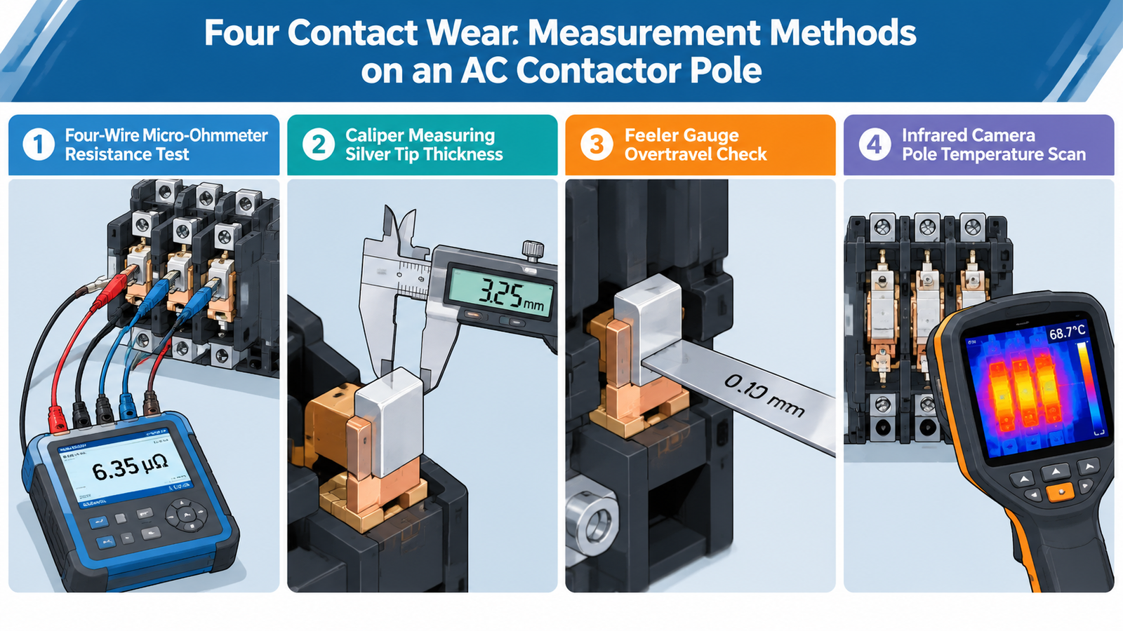
This guide gives the four measurable indicators — contact resistance, tip thickness, overtravel, and temperature rise — with the instruments, the threshold values, and the judgment lines between “replace contacts” and “replace contactor”. The material science behind why certain contacts erode faster is covered separately in the AgSnO2 vs AgNi vs AgCdO contact material comparison; here we stay on measurement.
Quick Answer: The Four Indicators and Their Limits
Indicator
Instrument
Healthy value (typical IEC frame)
Replace / investigate
Contact resistance
4-wire micro-ohmmeter (DLRO), 100 A preferred
50–500 µΩ depending on frame size (small frames lower, large frames higher)
> 2× the commissioning baseline, or > 1 mΩ on a frame measured in the hundreds of µΩ
Tip thickness remaining
Depth gauge / caliper on eroded pole
Full silver tip intact
< 1/3 of original tip thickness, or any base-metal exposure
Overtravel (wipe)
Feeler gauge / depth rod on manual actuation
Per datasheet (typically 2–4 mm on larger frames)
Near zero — contact springs bottoming out; contact about to fail open
Pole temperature rise
IR camera under ≥ 50% load, or thermocouple
Pole-to-pole ΔT < 5–10 K
One pole > 10 K hotter than its neighbors
Any single indicator past its limit is grounds for replacement; two together means the contactor has already been running degraded and the surrounding checks (coil, mechanism, arc chutes) need to happen before it goes back into service.
Indicator One: Contact Resistance (the 4-Wire Rule)
Contact resistance is the fastest field check, but it is also the most abused. A normal two-wire multimeter on the milliohm range reads its own lead resistance — which is the same order of magnitude as the contact you are measuring. The measurement is worthless unless the test current bypasses the leads: four-wire (Kelvin) measurement, with the voltage sense points on the contactor terminals themselves.
Field procedure:
Isolate and lock out the circuit; verify zero voltage across the poles.
Mechanically close the contactor (press the moving armature, or energize the coil from a safe test supply) so the contacts are in their normal seated position.
Connect the micro-ohmmeter’s current leads to the line and load terminals of one pole; clip the sense leads directly on the terminal pads, inside the current clamps.
Inject the rated test current (100 A class instruments are standard; if you only have a 10 A DLRO, record the current — contact films behave differently at low current, the “dry circuit” trap explained below).
Record per pole. Repeat identically each inspection — the trend matters more than the absolute number.
The dry-circuit trap: silver oxide and silver sulfide films are semiconductors. At high test current the film frits (breaks down) and the reading drops; at milliamp-level currents the film stays intact and the same contact can read 10–100× higher. A contact that reads 800 µΩ at 100 A and 40 mΩ at 10 mA is not necessarily bad — but a PLC-switched signal path through that same contact will misbehave. Measure at the current class your load actually represents, and compare like with like.
Localized erosion, contamination, or terminal loosening on that pole
Open and inspect that pole; check terminal torque first — it is the cheap cause
Reading unstable / drifting during test
Loose contact, broken spring, or severely eroded seating
Do not return to service before inspection
Indicator Two: Tip Thickness and Erosion Pattern
Resistance trends late; erosion is visible early. Silver contact tips on IEC frames are typically 1–3 mm thick depending on frame size, brazed or riveted to a copper backing. Erosion concentrates on one or two poles in three-phase devices because the arc does not share equally between breaks.
What to look for when the contacts are accessible (major overhaul, or after a suspected fault):
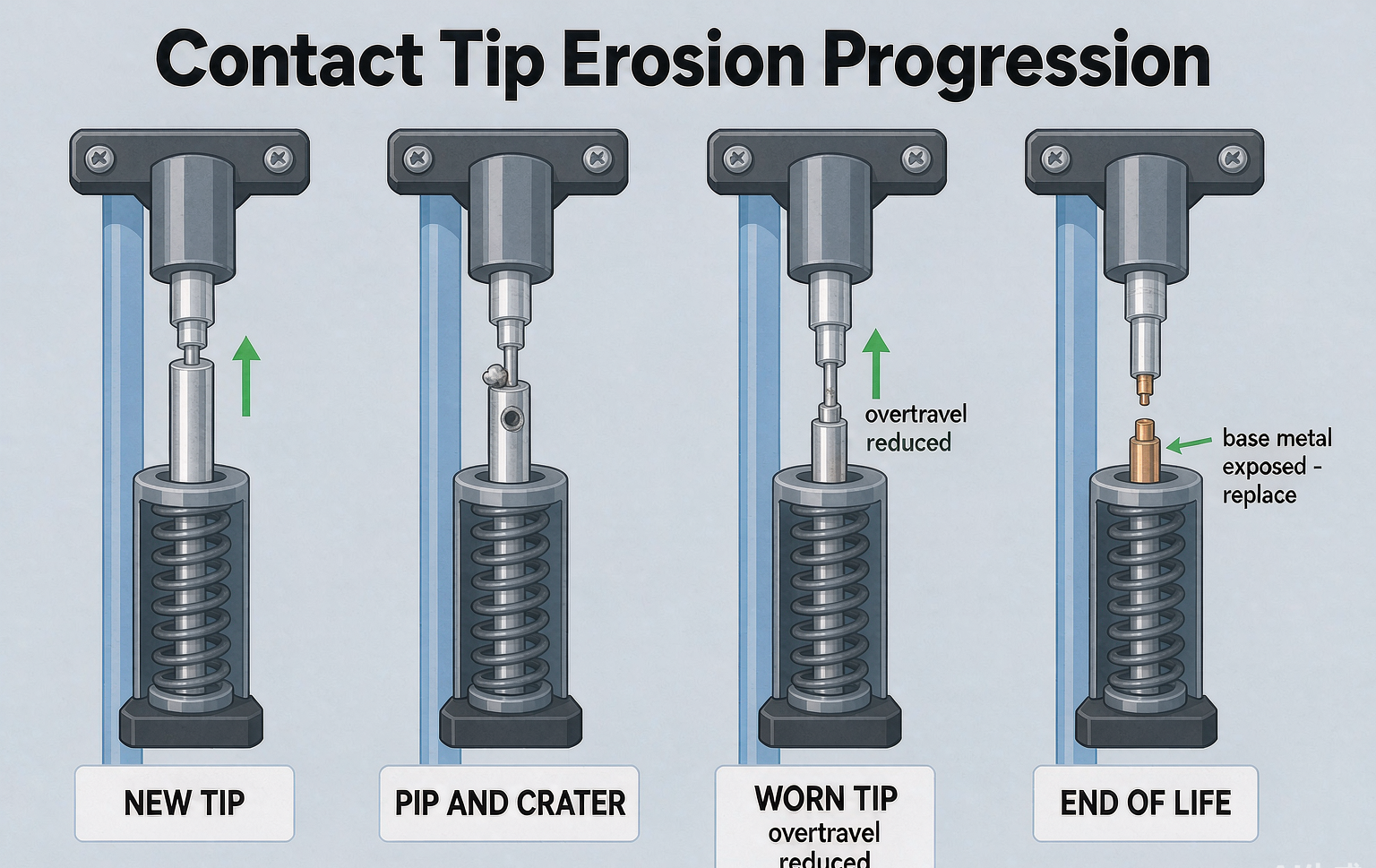
Even gray matte surface: normal. Silver oxide is fine — do not file it. The “do not abrade silver contacts” rule exists because you remove tip material every time; a blackened but smooth contact with stable resistance is a healthy contact. This is also why the preventive maintenance schedule calls for inspection and resistance trending rather than routine polishing.
Pip on one contact, crater on the other: classic make-erosion (material transfer during bounce). Progressive; measure the pip height against remaining thickness. Severe pips cause bouncing on every make, which accelerates the process — this is the wear mode that compounds.
Blackened, sooty deposits with carbon traces: arcing beyond design, usually from switching above the utilization category (an AC-3 contactor doing AC-4 work) or from a DC arc that the chute did not handle.
Base metal (copper color) visible through the silver: end of life. The contact will weld or fail within a short horizon; replace now, do not trend it.
Melted, welded, or deformed contact: this is a fault event, not wear. A welded contact pair means the contactor held a locked-rotor or short-circuit current it was never rated to interrupt — the coil, mechanism, and arc chutes have all seen the same event. Replace the whole contactor, not just the contacts. The distinction is set out in the contactor vs circuit breaker duty split: contactors are not short-circuit protection devices.
Indicator Three: Overtravel — the Measurement Nobody Takes
Overtravel (also called wipe or follow-through) is how far the moving contact travels after touching the stationary one. It exists so that contact spring pressure keeps the pair seated as the tip erodes. Every millimeter of tip erosion consumes overtravel; when the wipe reaches zero, the contacts touch with no spring force — high resistance, bouncing, welding on the next make.
Field check on larger frames (with the contactor isolated):
Actuate the contactor manually to just-close position; measure the gap from the moving contact carrier to its fully-seated position with a depth rod (typically 2–4 mm on 40 A+ frames).
Compare against the datasheet wipe dimension.
Less than half the datasheet value = plan replacement at the next window, even if resistance still reads fine.
Overtravel is the leading indicator of the group: it declines linearly with erosion while resistance stays flat until late-stage failure. Programs that track only resistance consistently get surprised by contact failures.
Indicator Four: Temperature Rise Under Load
With the panel live and carrying at least half its normal load, an IR scan of the contactor tells you which pole is working hardest. A pole running more than about 10 K above its neighbors is developing a hot spot — typically the terminal connection (loose lug, wrong torque) or an eroded contact interface raising I²R loss at that pole.
IR finding
Most likely cause
First action
Hot spot at the cable lug, not the contactor body
Terminal torque wrong or lug sized wrong
Re-torque to spec (cool), re-scan
Whole pole warm, symmetric line/load sides
Contact interface resistance rising
Confirm with 4-wire resistance on next shutdown
Coil area hot
Sealed coil current higher than expected — check coil voltage and mechanical friction
Check current with clamp meter; review contactor derating for the enclosure
The Judgement Line: Replace Contacts, or the Contactor?
Spare contact sets exist for the larger frames precisely because tip replacement is legitimate maintenance — but only when the rest of the device is sound. The decision line:
Condition found
Contacts only
Whole contactor
Erosion past 2/3 tip thickness, mechanism and coil healthy, no fault history
✔ Replace contact set; verify overtravel after reassembly
—
Contacts welded after a fault event
—
✔ The mechanism, coil and chutes saw the same current
Any base metal exposed on a tip
Only if the other poles are virgin and the event was minor
✔ Safer default on frames where contacts are riveted
Housing / arc chute carbon tracking or cracking
—
✔ Chute condition is not field-restorable
Small frames (≤ 32 A, economy class)
—
✔ Contact set cost vs device cost does not justify the labor
The last row is the one that saves the most debate: on compact frames, the contact set is a third of the device cost and the labor exceeds the saving. Contact replacement is an economic decision above roughly 40 A frames, and a false economy below.
Setting Wear Limits That Actually Work
Thresholds belong in the maintenance record, not in memory. For each contactor in the plan, log at commissioning: contact resistance per pole at a fixed test current, overtravel (if measurable), and a photo of the contact faces. Then set:
Resistance alarm: 2× commissioning baseline on any pole.
Thickness action point: 1/3 remaining tip thickness → replace contacts at next planned window.
Overtravel action point: 50% of datasheet wipe → order contact set; near-zero → replace now.
Operation count review: every 100,000 operations on AC-3 duty (or per the duty-class table in the maintenance schedule), pull a sample contactor for physical inspection — resistance alone does not reveal pips.
AC-4 applications (plugging, jogging, reversing) erode contacts 10–20× faster than AC-3; the same inspection interval that is generous on a pump starter is negligent on a hoist. The category definitions that set this ratio are in the AC-1 to AC-4 guide.
Common Mistakes
Mistake
Consequence
Correct practice
Measuring contact resistance with a 2-wire multimeter
Reading dominated by lead resistance; meaningless trend
4-wire DLRO with sense points on the terminals, fixed test current
Filing or sanding silver contacts “to clean” them
Removes tip material; new sharp edges increase bounce; shortened life
Leave the film; track resistance instead
Replacing only the welded pole’s contact after a fault
Asymmetric erosion and resistance; the unwelded poles carry the same fault history
Replace all poles as a set; audit the whole device
Ignoring overtravel because it is not on the checklist
Zero-wipe failure arrives without any resistance warning
Add wipe to the inspection sheet for frames ≥ 40 A
Trending resistance across different test currents
Film fritting makes 10 A and 100 A readings incomparable
Fix the test current; record it with each reading
Conclusion
Contact wear is measurable long before it fails: resistance for the electrical trend, thickness and overtravel for the mechanical trend, IR for the live cross-check. Track all four with fixed instruments and baselines, replace tips as a set on large frames while the mechanism is still healthy, and treat any welded or base-metal-exposed contact as a whole-device event rather than a consumable swap. For the erosion physics behind the patterns above, see the contact material comparison; for the internal construction these tips mount on, see inside an AC contactor; and for replacement contact sets across CJX2/CJX4 and CJ35 frames, browse the contactor contacts range or the wider AC contactor category.
FAQ
How often should contactor contacts be inspected?
Baseline annually for AC-3 duty, every 6 months for AC-4 or dusty environments, and physically (contacts out of the device) every 100,000 operations or per the duty-class maintenance table. Electrical resistance checks can be more frequent since they are non-invasive.
What is a normal contact resistance value?
Small frames typically measure tens to low hundreds of micro-ohms; large 200 A+ frames run into the hundreds of µΩ. The absolute number matters less than stability against your own commissioning baseline at the same test current.
Can I clean blackened silver contacts with sandpaper?
No. Abrading removes silver tip material and creates sharp edges that bounce on make, accelerating erosion. A dark oxide film with stable resistance is normal; file nothing, replace by measurement.
When must I replace the whole contactor instead of just contacts?
After any welded-contact fault event, when arc chutes are cracked or carbon-tracked, when base metal is exposed on the tips, and on small frames where contact-set cost plus labor exceeds device cost.
Why does one pole always wear faster than the others?
Three-phase arcs do not distribute symmetrically between breaks, and make-bounce concentrates transfer on specific pole pairs. This is why wear limits apply per-pole and why sets are replaced together.
Does contact wear affect the overload relay setting?
Indirectly. Rising contact resistance adds heat into the pole circuit and, in severe single-pole erosion cases, contributes to current imbalance that the differential-amplified thermal relay may respond to. Severe wear should be corrected before it reaches the protection chain described in the thermal overload relay guide.
Input side sees harmonics, output side sees PWM — and neither contactor should do the drive's job. Selection margins, sequencing rules, bypass interlocking, and the DC paths where AC contactors must not go.
The full reversing starter: power wiring with two phases swapped, cross-coupled NC electrical interlock, mechanical interlock backstop, 50–100 ms dead time, and why weld detection is the layer no interlock provides.
Resistance screens the winding, pickup voltage proves it will seat on a sagging bus, drop-out proves it will release. Reference bands, IEC windows, and the five root causes behind burnt coils.